Start with the Airport Electrical Mission
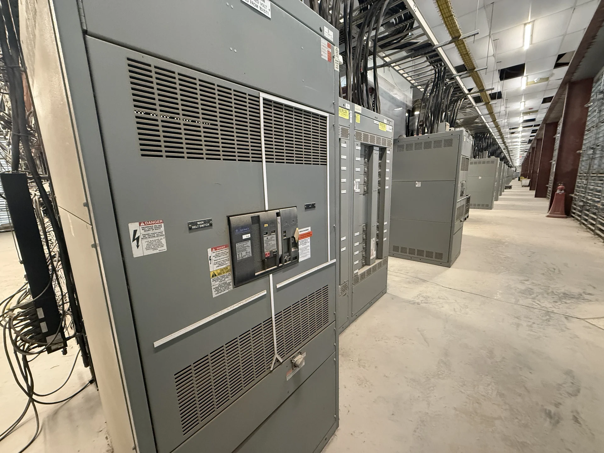
Airport power distribution is shaped by more than connected load. A terminal, hangar, airfield support building, baggage system, maintenance facility, or navigation-related installation can have different continuity priorities and operating constraints. Begin with a current one-line diagram, source description, nominal voltage, phase and wire arrangement, grounding method, available fault current, calculated loads, and future expansion assumptions. Identify which circuits are ordinary, standby, legally required, or project-designated critical loads. That information lets a manufacturer evaluate whether a new switchgear lineup, switchboard, transfer interface, or coordinated combination is appropriate rather than treating every airport project as the same application.
Coordinate Terminal and Airfield Interfaces
Airport electrical equipment often sits at the intersection of utility service, generators, automatic transfer equipment, UPS systems, lighting controls, mechanical loads, and communications or security infrastructure. The design team should document where each source enters the distribution system, which buses may be tied, and what operating sequence governs transfers and restoration. For airfield support facilities, include outdoor exposure, cable routing, equipment access, and site interfaces in the equipment inquiry. For terminals, review room dimensions, delivery paths, working clearances, maintenance access, and the effect of phased construction on the final lineup.
Define Protection and Switching Requirements
A useful airport switchgear specification connects every protective device to a defined duty. List continuous current, interrupting or withstand requirements as applicable, voltage class, feeder destinations, breaker or fused-switch preferences, metering points, control power, and any required communications. A qualified engineer can use available-fault-current data and a coordination study to assess device ratings and settings across mains, ties, and feeders. If generator sources or paralleling are involved, provide the intended sequence, interlocks, synchronizing responsibilities, grounding arrangement, and emergency operating modes. These inputs reduce ambiguity when custom equipment is engineered to project documents.
Plan for Critical Load Continuity
Backup power planning should describe the consequence of an interruption for each airport load, not simply label an entire building critical. Separate loads may require different transfer behavior, source priority, ride-through expectations, or restoration procedures. Document whether a load is served from a normal source, generator, UPS, or more than one path, and show how downstream equipment interacts with the switchgear. The project should also establish manual operating procedures, key interlocks, remote indications, alarm points, and control-panel interfaces. Final decisions belong to the responsible electrical engineer and the authorities or utility stakeholders applicable to the project.
Build a Complete Manufacturer Inquiry
When requesting a quote for new airport switchgear, send the one-line diagram, equipment schedules, floor plan or room dimensions, source data, feeder list, control narrative, metering requirements, environmental conditions, connection points, and desired documentation. State whether the equipment is indoor or outdoor, how sections must be divided for shipping, where cable enters, and how the assembly will be moved into position. Switchgear Builders manufactures custom new electrical switchgear in the United States, uses American components, and supplies equipment with nationwide shipping. The quotation should still confirm the exact scope, component selections, drawings, testing, commercial terms, and project-specific delivery expectations.
Review Drawings, Testing, and Delivery Details
Before fabrication, review the approved arrangement, elevations, nameplate information, bus configuration, protective devices, control wiring, terminal assignments, and source interlocks against the airport design. Establish which inspections, continuity checks, insulation checks, functional demonstrations, and records are required, along with witness participants and acceptance criteria. If the specification references UL 891, confirm whether it applies to the particular assembly and what project-specific listing or verification is required; applicability cannot be assumed from the equipment name alone. Coordinate packaging, lifting points, shipping splits, receiving inspection, storage conditions, and qualified installation responsibilities before release.