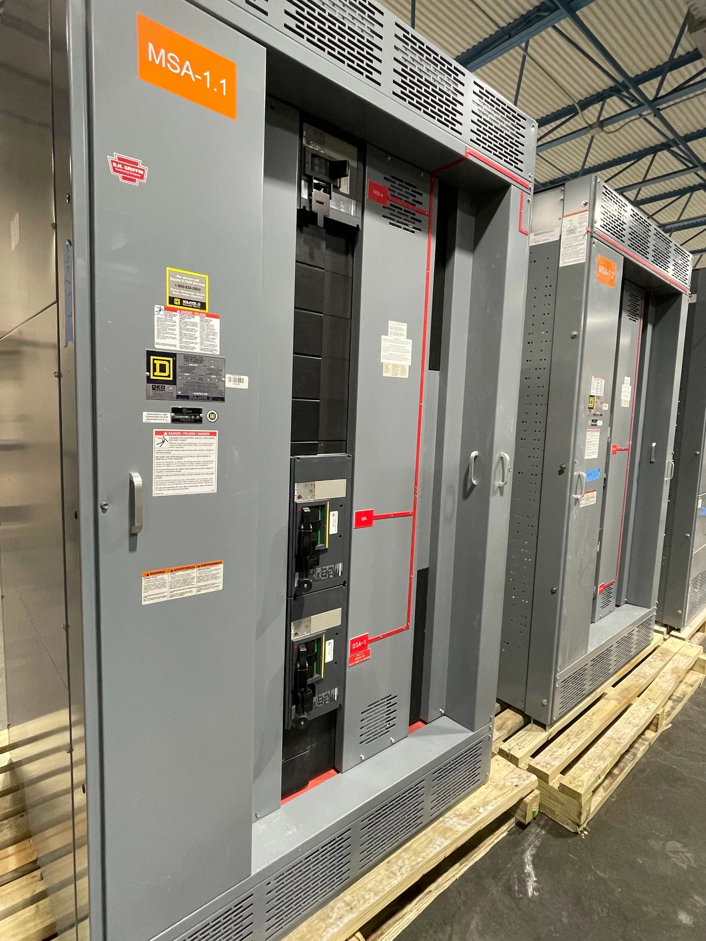
Start With the Electrical and Physical Requirements
Switchgear manufacturing begins before metal is cut or a breaker is installed. A useful equipment definition brings together the single-line diagram, nominal voltage, phase and frequency, continuous current, available fault current, grounding method, feeder count, protective-device duties, enclosure environment, and required operating sequence. Physical information matters just as much: lineup dimensions, cable-entry direction, room access, working clearances, lifting constraints, and connection points can determine whether a sound electrical concept can be installed in the intended space. Switchgear Builders manufactures new electrical switchgear in the United States, custom to specification, using American components and arranging nationwide shipping. The project team should confirm each input with the responsible electrical engineer and installation professionals before fabrication begins.
Engineering Turns Project Data Into Buildable Drawings
Engineering translates the requirement into an equipment arrangement that can be reviewed, fabricated, wired, and maintained. Designers coordinate the bus layout, main and feeder devices, metering locations, control power, terminal points, barriers, doors, removable panels, cable compartments, and grounding provisions. They also examine selective coordination information, protection settings, interlocks, source-transfer logic, and the interfaces between the lineup and connected conductors. Submittal drawings should make assumptions visible rather than hiding them in a generic outline. For a custom switchgear project, the review cycle is the opportunity to resolve conflicting dimensions, identify missing ratings, and document which design choices remain subject to field or authority review. UL 891 applicability, along with any project-specific listing or construction requirement, must be confirmed for the particular assembly rather than assumed from the product name.
Fabrication Creates the Enclosure and Structural Framework
Fabrication converts approved drawings and selected materials into the enclosure and structural parts that support the electrical assembly. Work can include material preparation, forming, drilling, joining, door and panel fitting, mounting provisions, barrier installation, surface preparation, and finish coordination. Accuracy is practical, not cosmetic: a misplaced opening can interfere with cable bending space, an inconsistent panel fit can complicate access, and inadequate support planning can affect the installation interface. The fabrication plan should account for transport sections, lifting points, shipping dimensions, field-join locations, ventilation needs, and the environment identified for the equipment. Engineers and installers should review unusual access or foundation conditions early, while the manufacturer keeps the physical build aligned with the approved electrical arrangement and documentation.
Buswork, Devices, and Control Wiring Become One Assembly
Assembly brings the enclosure, bus conductors, protective devices, metering, control components, and wiring together as a coordinated lineup. Buswork requires deliberate attention to conductor sizing, joints, supports, clearances, phase identification, insulation where specified, and connection hardware. Device installation must preserve access for operation and maintenance while matching the drawings and the specified electrical duties. Control wiring benefits from consistent terminal identification, clear routing, segregation from power conductors where required, and a clear relationship to the control schematic. Interlocks and source logic should be checked against the intended sequence, especially when a main-tie-main or other multi-source arrangement is involved. A custom build is successful when the physical assembly, wiring records, and operating concept describe the same equipment.
Inspection and Testing Establish Documented Checks
Inspection and testing should follow a project-defined plan instead of a vague promise that equipment was checked. Visual and dimensional inspection can address workmanship, labels, fasteners, barriers, clearances, device identification, wire termination, grounding continuity, and correspondence with approved drawings. Electrical checks may include continuity, insulation-related measurements, polarity or phase verification where applicable, and control-circuit functional checks, with methods and acceptance criteria agreed for the project. Functional review can exercise the specified interlocks, indications, alarms, and operating sequence without assuming a particular test result in advance. Results should be recorded in a package that identifies the equipment, test conditions, instruments or methods where required, exceptions, and final disposition. Any witness or factory-acceptance requirements should be agreed before the inspection event.
Packaging and Delivery Complete the Manufacturing Process
Project delivery extends beyond completing the lineup. The shipping plan should define section splits, weights, dimensions, lifting provisions, protection against handling damage, moisture or contamination controls, labels, hardware packaged separately, and the documents that travel with the equipment. Destination information affects freight coordination, unloading access, receiving responsibilities, and whether a qualified rigging plan is needed. Nationwide shipping from an American manufacturer still requires project-specific coordination: the buyer should confirm the delivery address, site restrictions, requested freight terms, receiving hours, storage conditions, and who will inspect the shipment on arrival. Before energization, the installing team should compare received sections with the drawings, inspect for transit damage, verify field connections, and complete the commissioning checks assigned by the project engineer.