Start with the Plant Distribution Study
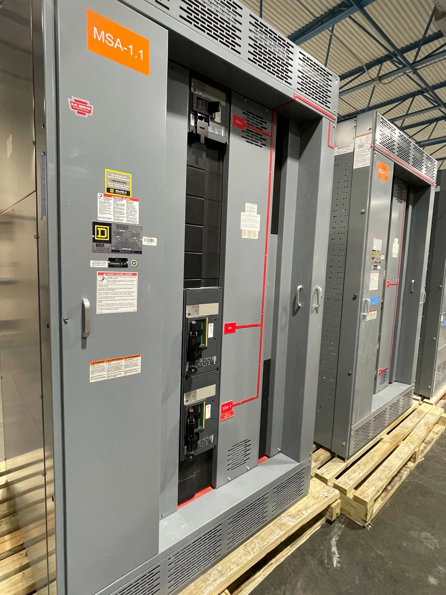
Switchgear for industrial plants and manufacturing begins with the facility’s electrical distribution study, not a catalog label. The design team should identify utility or generator sources, nominal voltage, phase and frequency, grounding method, continuous loads, motor starting conditions, and available fault current. From there, the lineup can be defined around main devices, feeder circuits, bus sections, and future capacity. A useful inquiry also identifies whether equipment will serve process loads, general plant services, or both. Those distinctions influence protection, metering, compartment arrangement, cable entry, and the interfaces that installers must coordinate before fabrication. For a plant with several voltage levels, identify which loads share a bus and which require transformers or separate feeder sections; that mapping exposes important interfaces.
Coordinate Motor Loads and Starting Methods
Industrial plants often combine large motors with conveyors, pumps, compressors, heaters, drives, and controls. Each load type affects feeder protection and the operating sequence of the electrical system. A motor schedule should show horsepower or kW, voltage, full-load current, starting method, duty, acceleration needs, and whether a variable frequency drive or starter is specified. The switchgear layout must leave a clear path for power and control conductors while accommodating ventilation, separation, terminal access, and maintenance space. Protective settings remain an engineering decision based on the complete system rather than a generic motor category. Record nuisance-tripping concerns separately from legitimate fault protection, and note whether drives impose bypass, harmonic, or line-side requirements. These details align feeder compartments with the control architecture.
Build Around Production Continuity
Production continuity is best addressed by defining how the plant should respond to an outage, fault, inspection, or planned shutdown. Engineers may evaluate separate buses, main-tie-main arrangements, selective feeder isolation, standby generation interfaces, or dedicated distribution for critical processes, but the suitable arrangement depends on the one-line diagram and operating philosophy. Ask which loads may stop, which must transfer, and which cannot restart simultaneously. Interlocks, control power, communication points, and local operating controls should be documented in the sequence of operations so the manufacturer can translate the intent into a custom new assembly. A restart matrix can show load priority, permissive signals, and intentional delays without prescribing settings before study work is complete. It gives commissioning personnel a reference for checking the intended sequence.
Account for the Manufacturing Environment
The plant environment can change enclosure and layout decisions. Dust, moisture, washdown, corrosive chemicals, heat, vibration, indoor temperature, and outdoor exposure should be described with the installation location rather than assumed from the industry name. The specification should also address equipment-room access, working clearances, floor loading, cable routing, conduit positions, lifting paths, and anchorage interfaces. A qualified project team can then determine the applicable enclosure type, materials, finish, ventilation, and environmental provisions. These inputs are especially important when a lineup must fit an existing room or be divided into shipment sections. If production areas expand in phases, mark reserved sections, spare conduit paths, and access zones on the room drawing. Coordinating those allowances early helps before enclosure dimensions are frozen.
Define Ratings, Documentation, and Verification
A complete equipment schedule should state continuous current, voltage class, short-circuit duty, bus material, protective-device types, metering, control voltage, wiring points, and required dimensions. The project should identify the governing standards and whether UL 891 applies to the particular switchboard or assembly; applicability and any listing or capability must be confirmed for that project. Drawings, bills of material, device data, wiring diagrams, test procedures, and recorded results should be assigned as submittal requirements. This disciplined review helps the manufacturer build to the approved design instead of filling critical gaps with assumptions.
Purchase a Custom-Built U.S. Equipment Package
Switchgear Builders manufactures, builds, and supplies new electrical switchgear in the United States, custom to specification, using American components and nationwide shipping for customer projects. To request a useful quote, provide the latest one-line diagram, load and motor schedules, fault-current information, site conditions, dimensions, cable details, control narrative, documentation requirements, destination, and requested commercial terms. The resulting scope should identify inclusions, exclusions, approvals, testing, packaging, shipping responsibilities, and installation interfaces. Engineers, contractors, and plant owners should review the final design and project requirements before release for fabrication.