Start with the Plant One-Line and Operating Sequence
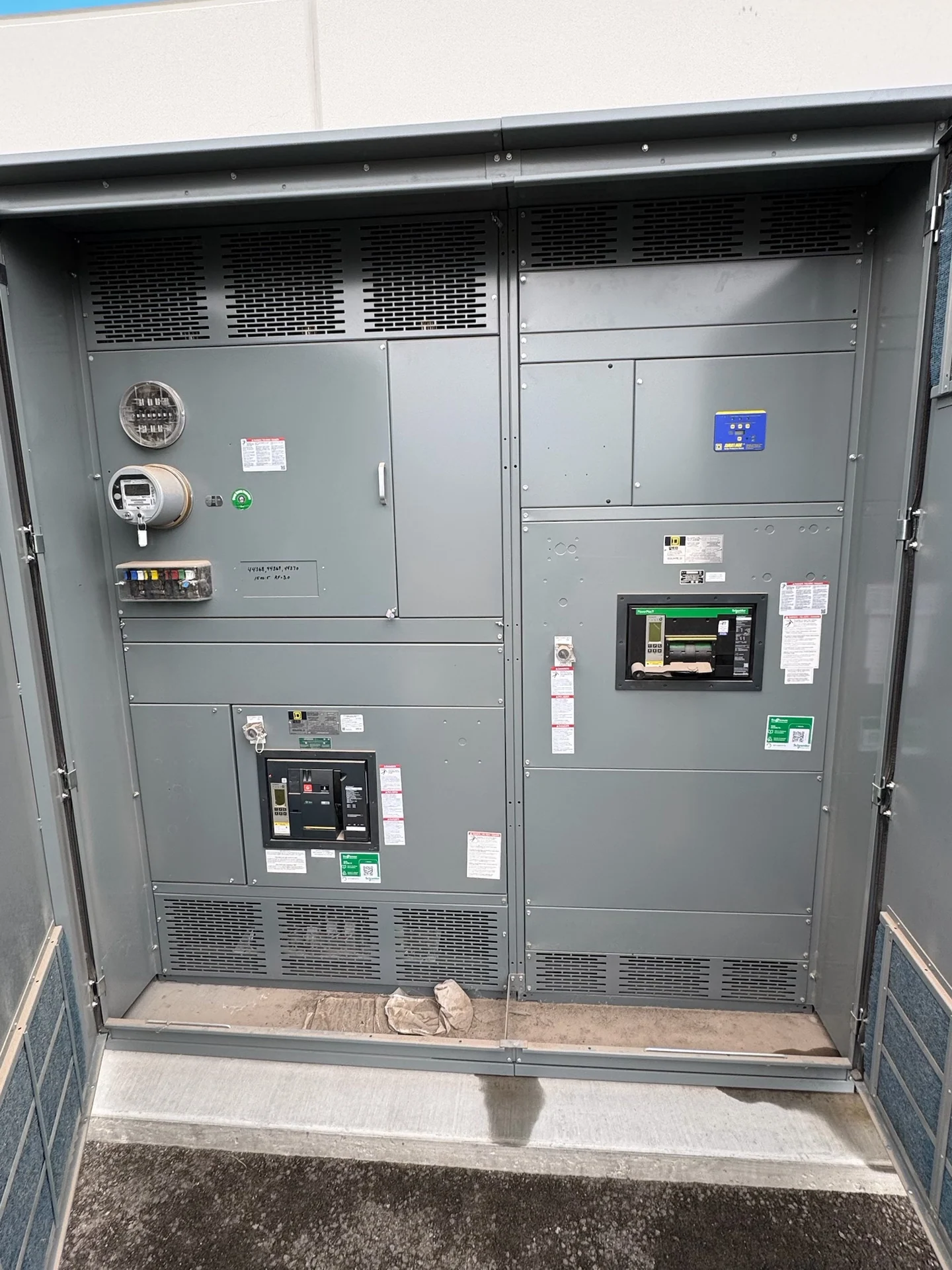
Power plant switchgear has to fit the way sources, generators, transformers, auxiliary buses, and outgoing feeders operate together. A useful specification begins with the current one-line diagram, normal and alternate source paths, generator interconnection points, grounding method, synchronization requirements where applicable, and the intended sequence during startup, shutdown, transfer, and fault isolation. Switchgear Builders manufactures new electrical switchgear in the United States, custom to project requirements, using American components and supplying equipment with nationwide shipping. The final arrangement should be reviewed by the responsible electrical engineer so equipment functions match the plant control philosophy rather than relying on a generic lineup.
Generator Interfaces and Source Coordination
Generator switchgear interfaces can include generator breakers, bus ties, feeder breakers, metering, protective relays, synchronizing functions, and connections to a utility or plant distribution bus. The design team should identify whether sources operate independently, in parallel, or under a defined transfer sequence, then document permissives, interlocks, breaker status points, trip signals, and control power requirements. Generator neutral treatment, grounding transformers, excitation or synchronizing interfaces, and protection zones may affect the equipment design. These items are project-specific; a manufacturer can build to an approved schematic, but the operating sequence and protection settings must come from qualified engineering review.
Auxiliary Loads Need Their Own Distribution Logic
Boiler or turbine auxiliaries, pumps, fans, cooling systems, lubrication equipment, emissions controls, battery chargers, and plant controls can create a varied mix of continuous, intermittent, motor, and sensitive electronic loads. Define which loads are essential, which can shed, and which require an alternate source before selecting mains, feeders, ties, or transfer equipment. Motor starting current, large drive loads, harmonics, voltage sensitivity, and available space for future circuits can influence bus capacity and protective-device choices. A practical switchgear package separates documented load assumptions from confirmed requirements, allowing the lineup, wiring, metering, and control interfaces to be checked against the plant distribution study.
Ratings, Protection, and Fault-Duty Inputs
Specify nominal voltage, frequency, phase and wire configuration, continuous current, short-circuit duty, interrupting ratings, insulation requirements where applicable, enclosure environment, and equipment grounding details. Available fault current should be calculated at each relevant bus, including contributions from generators, utility sources, motors, and transformers. Protective coordination requires time-current information, relay functions, breaker trip settings, transformer data, and the desired selectivity between generator, main, tie, and feeder devices. The equipment rating is not established by the plant name alone. It must be selected and documented for the actual electrical system, operating modes, and project requirements.
Construction, Controls, and Verification
A custom lineup should be reviewed for compartment arrangement, bus routing, cable entry, maintenance access, control-wire segregation, terminal identification, lifting provisions, and the physical path into the plant. Drawings should show device labels, interlock logic, wire numbers, metering locations, communications points, and interfaces to the plant control system. Inspection and testing should follow an agreed project plan covering workmanship, dimensions, wiring continuity, insulation checks where appropriate, device operation, and documented results. If a specification references UL 891, confirm whether it applies to the particular assembly and verify any project-specific listing or capability before order approval; it should never be assumed from a general equipment description.
Plan Delivery Around Site and Commissioning Constraints
Power plant equipment may need shipping sections sized for access roads, doors, cranes, rigging, and the final electrical room or outdoor foundation. Provide destination details, receiving hours, unloading responsibilities, lifting limits, shipping splits, and protection against moisture or handling damage during freight planning. The installation team should align factory documentation, cable schedules, settings files, inspection records, and commissioning activities with the outage or construction plan. Switchgear Builders can coordinate new custom equipment for nationwide shipment, while project participants remain responsible for confirming site readiness, qualified installation, field connections, and the final energization process.