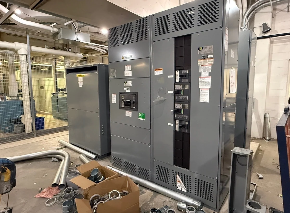
Start With the Generator and Distribution Architecture
Power plant generator switchgear interfaces begin with a clear map of how each generator connects to the plant bus, auxiliary loads, transformers, utility interconnection, and alternate sources. The one-line diagram should identify generator terminals, feeder paths, bus sections, main and tie devices, grounding points, and any synchronizing locations. A manufacturer can build new custom switchgear to that defined architecture, using American components and coordinating the physical lineup with cable entry, maintenance access, and installation boundaries. The equipment request should distinguish generator breakers from feeder breakers and state whether the lineup serves one source, multiple units, or a coordinated plant distribution scheme.
Define Feeder Switching Duties
Feeder switching must reflect what the generator and connected system are expected to do during starting, normal loading, transfer, isolation, and fault conditions. Specify nominal voltage, continuous current, available fault current, interrupting or withstand requirements, frequency, phase arrangement, grounding method, and the operating sequence for each main, feeder, and tie device. Generator applications may require separate treatment of generator output feeders, station-service feeders, motor loads, and transformer feeders. These inputs let Switchgear Builders develop a new assembly around the plant design instead of treating a generic switchgear lineup as a substitute for system engineering.
Coordinate Protection and Control Interfaces
Protection coordination connects the generator, switchgear, transformer, and downstream feeder settings into one reviewed scheme. Project documents should identify protective relays or trip units, sensing locations, current-transformer data, breaker control voltage, trip and close circuits, lockout functions, alarm contacts, and communications requirements where applicable. Engineers should evaluate generator contribution, transformer inrush, motor starting, reverse power, loss of excitation, overcurrent, ground-fault, and voltage or frequency conditions as appropriate to the plant design. The switchgear design can then reserve space, terminals, barriers, and wiring paths for the specified devices and control logic without assuming a particular relay package.
Plan Grounding and Synchronization Together
Grounding and synchronization are interface questions, not isolated accessory selections. The project team should document generator neutral treatment, grounding transformers or resistors if applicable, equipment grounding conductors, ground bus connections, bonding points, and the relationship between source grounding and protection sensing. For paralleling or closed-transition operation, the control narrative should state who permits breaker closure, how voltage, frequency, phase angle, and phase sequence are checked, and what inhibits operation when conditions are not acceptable. A qualified engineer must review the sequence, while the manufacturer translates approved logic into devices, terminals, interlocks, and drawings.
Coordinate Physical Construction With the Plant
Generator interfaces also depend on practical construction details that are easy to omit from an electrical schedule. Provide lineup dimensions or room constraints, shipping splits, cable routing, entry direction, bus orientation, lifting provisions, heat and ventilation conditions, enclosure environment, seismic or anchorage criteria when specified, and the path from receiving to the electrical room. Confirm how generator conductors, control cables, fiber, metering circuits, and external emergency-stop or annunciation wiring will terminate. New custom switchgear should be reviewed against the approved drawings and installation responsibilities before fabrication, with field connections and commissioning activities clearly assigned among the project participants.
Prepare a Complete Manufacturer Inquiry
A useful inquiry for power plant generator switchgear interfaces includes the latest one-line diagram, load and fault studies, generator data, transformer information, protection and control narrative, sequence of operations, interconnection requirements, physical dimensions, environmental conditions, cable schedules, metering needs, and required documentation. State which items are furnished by others and identify review milestones for drawings, wiring, testing, and shipment. Switchgear Builders produces new switchgear in the United States to custom specifications, using American components and offering nationwide shipping. Project-specific requirements, including whether UL 891 applies and what evidence is needed, must be confirmed before the equipment scope is finalized.