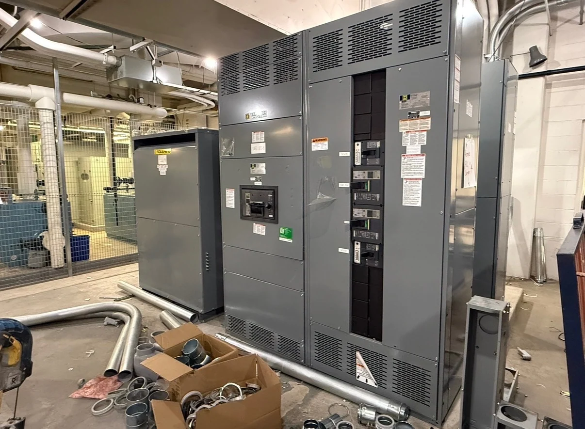
Start with the Tucson Industrial Load Profile
Industrial motor control centers in Tucson, Arizona should be defined from the actual operating loads rather than selected from a generic lineup description. Begin with the motor schedule for pumps, conveyors, fans, compressors, and process machinery, including horsepower, voltage, phase, full-load current, starting method, duty cycle, and whether each load is continuous or intermittent. Note ambient conditions, elevation considerations, indoor or outdoor placement, dust, moisture, washdown exposure, and available room space. A clear load profile lets the manufacturer distinguish motor starters, feeder sections, and control compartments while leaving room for engineering review of the complete distribution system. For a Tucson plant, separate the motor list by process area so a pump skid, conveyor group, or dust-collection fan bank can be traced to its feeder and control points. Flag motors that may restart together, cycle frequently, or operate during planned source transfers; those details affect sequencing and the review of voltage disturbance and protective settings. If drives serve long runs, identify cable routes and motor locations early, since termination space, grounding practices, and noise-control requirements may influence the lineup and field installation. Record whether each process area has local isolation, washdown routines, or restricted access, because those operating practices shape service access and labeling.
Choose Starters, Drives, and Protection Deliberately
The control method should follow the process requirement and the motor's operating behavior. Across-the-line starters may suit some straightforward motors, while reduced-voltage starters or variable frequency drives can be considered where starting current, acceleration, speed control, or process sequencing matters. Each bucket affects heat, wiring, enclosure arrangement, maintenance access, and coordination with upstream protective devices. Specify overload characteristics, short-circuit protection, disconnecting means, control voltage, bypass needs, and fault-current information as applicable. The final selection requires review by the responsible electrical engineer and confirmation that every device is suitable for the stated system conditions.
Define the Control Interface Before Quoting
A useful custom switchgear quote needs more than a list of motors. Describe how the motor control center will exchange status, commands, permissives, alarms, and trips with the plant control system. Identify hardwired points, network communications, local controls, remote stations, emergency-stop circuits, interlocks, and the normal state of each contact. Provide I/O lists, control schematics, sequence narratives, communication requirements, and naming conventions when available. These inputs help a manufacturer organize terminal locations, wire numbering, segregation, and testing records without assuming a particular automation platform or promising a feature that the project documents do not require.
Coordinate Layout, Environment, and Installation
Tucson project conditions can make physical coordination as important as electrical selection, so document the intended room or process area carefully. Confirm lineup dimensions, section boundaries, cable entry direction, feeder routing, ventilation, access doors, working clearances, lifting or handling constraints, and the path from receiving to the installation point. For outdoor or exposed locations, identify enclosure and environmental requirements based on the site conditions and applicable project specifications. The equipment layout should also account for future circuits, spare spaces, wireway capacity, drive heat dissipation, and the installer’s termination approach before drawings are finalized.
Use Consistent Technical Inputs for a Custom Build
When requesting industrial motor control centers, send the one-line diagram, motor schedule, available fault-current information, system voltage and frequency, grounding method, enclosure requirements, control documents, and relevant site drawings together. Include the desired lineup arrangement, nameplate data, feeder destinations, metering points, documentation expectations, and any planned inspection or functional test scope. Switchgear Builders manufactures new electrical switchgear in the United States, builds custom to specification, uses American components, and supplies equipment with nationwide shipping. Project-specific availability, configuration, shipping details, and any applicable standard or listing requirement must be confirmed for the individual order.
Plan Review, Testing, and Field Coordination
Before release for fabrication, compare the approved drawings against the motor schedule, control sequence, physical dimensions, and installation responsibilities. Establish who will provide field wiring, network configuration, protection settings, startup, and site acceptance activities. A project test plan may include visual inspection, point-to-point checks, continuity checks, insulation checks where appropriate, device operation, interlock verification, and documentation of agreed results; the exact scope belongs in the project documents. Coordinate receiving, storage, rigging, terminations, and commissioning with qualified site personnel so the new lineup arrives with clear interfaces rather than unresolved assumptions.