Plan the Fort Wayne Electrical Distribution Scope
A Fort Wayne, Indiana switchgear project should begin with the facility's actual distribution study rather than a product name alone. Identify the utility source, generator or other alternate source, service voltage, phase arrangement, grounding method, available fault current, continuous loads, and future capacity assumptions. Then map which critical facility loads require automatic transfer switches, which loads may remain on normal power, and how the proposed equipment connects to downstream switchboards, motor control centers, transformers, and panelboards. This information gives a manufacturer a workable basis for a new custom lineup and helps the engineer distinguish source-transfer requirements from ordinary feeder protection.
Match Automatic Transfer Switches to Critical Loads
Automatic transfer switches for critical facility loads should be selected around the load behavior and the consequences of source interruption. A healthcare area, communications room, process pump, life-safety system, or temperature-sensitive installation can require a different transfer sequence, control interface, or source arrangement. Document whether the transfer is open transition, whether a bypass-isolation arrangement is needed, how the alternate source is started, and what return-to-normal conditions apply. The design team should also state acceptable voltage and frequency sensing behavior, time delays, manual controls, annunciation, and any coordination with building automation or generator controls before fabrication begins. For a Fort Wayne site, document whether critical loads are concentrated in one building or distributed across campus feeders. That distinction affects feeder routing, selective transfer choices, and where maintenance bypass provisions can be accessed without entering restricted spaces. Coordinate the sequence with the authority having jurisdiction and the commissioning plan, while leaving final settings to the responsible engineer.
Review Source Capacity and Protection
Source capacity must be checked on both sides of the transfer equipment, including normal service limitations and alternate-source generator capability. Compare calculated demand, motor starting effects, transformer inrush, nonlinear loads, and planned expansion with the continuous current ratings of mains, bus, feeders, and transfer devices. Available fault current at each relevant point should be established by the project's electrical study, then compared with breaker interrupting ratings and the assembly's specified short-circuit duty. Protective-device coordination should account for both source conditions, because settings that coordinate on utility power may behave differently when a generator supplies the critical bus.
Coordinate the Physical Installation
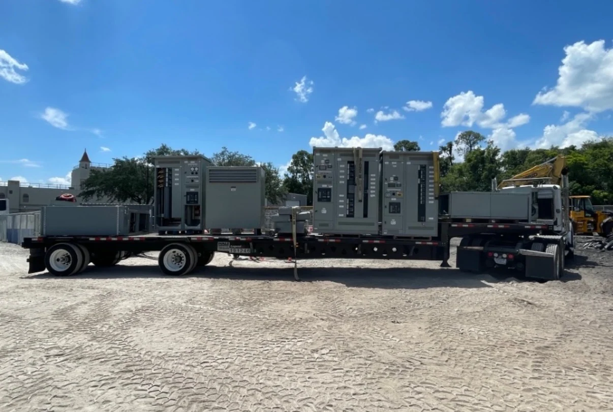
A practical Fort Wayne equipment package also depends on dimensions and installation interfaces. Confirm the electrical room footprint, working clearances, door swings, cable entry, bus or feeder connection points, ventilation needs, lifting route, floor loading, anchorage details, and access for inspection or future maintenance. If the equipment must be divided into shipping sections, identify the site path and rigging responsibilities early. The manufacturer can use approved drawings, the one-line diagram, wiring schedules, and interface details to develop new custom switchgear and associated transfer equipment that fits the documented project constraints rather than forcing field modifications after delivery. Ask the installer to mark cable bend space and termination heights on the reviewed layout; those dimensions can determine whether a lineup fits the existing room without relocating raceways. Include spare conduit routes and labeled test points when future expansion or recurring transfer tests are part of the operating plan.
Define Testing and Documentation
Before ordering, agree on the inspection and test plan for the particular assembly. Useful records may include dimensional checks, wiring verification, continuity checks, insulation checks where applicable, device settings, control-power checks, source-simulation steps, transfer and retransfer operation, alarm indications, and interlock verification. Acceptance criteria, witness points, test instruments, and responsibilities should be written into the project documents instead of assumed. If UL 891 is specified for a switchboard application, confirm its applicability, construction requirements, and any project-specific listing or evidence with the responsible parties.
Request a Manufacturer-Built Quote
To request a useful quote for Fort Wayne electrical distribution, send the manufacturer the latest one-line diagram, load schedule, source data, fault-current information, transfer sequence, control narratives, physical dimensions, environmental conditions, connection preferences, documentation list, destination, and desired review milestones. Switchgear Builders manufactures new electrical switchgear in the United States, builds custom to specification with American components, and ships nationwide. Engineering review should document the final scope, component details, shipping terms, and applicable requirements for the specific site and application.