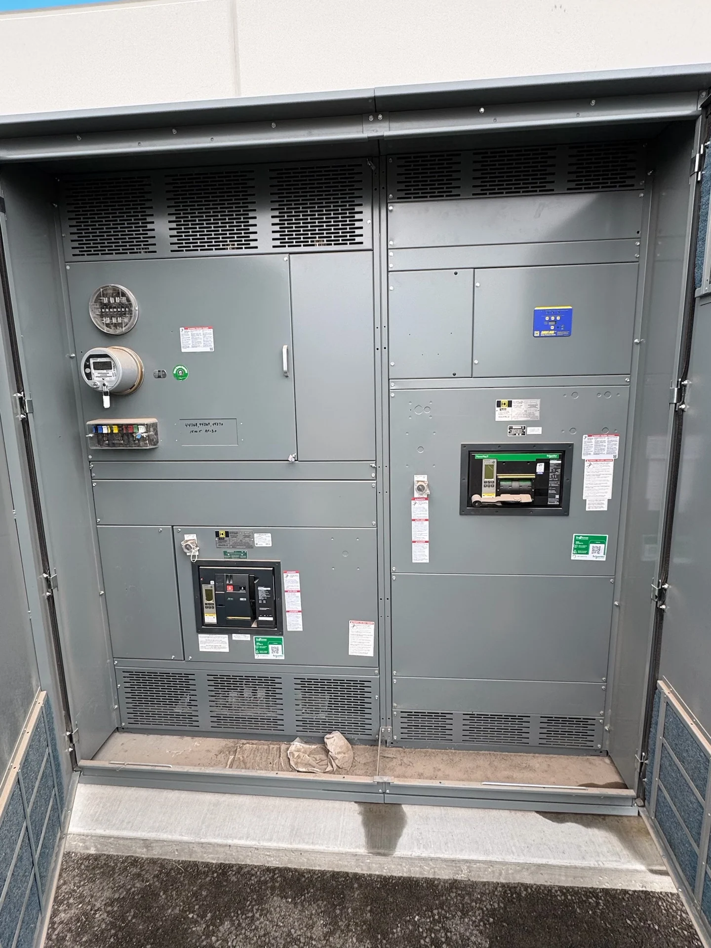
Plan Omaha Data Center Distribution Around the Power Path
An Omaha, Nebraska data center distribution project should begin with a clear map of every electrical path, from utility service and generator sources through switchgear, transformers, UPS equipment, and final loads. The one-line diagram should identify normal and alternate sources, bus sections, ties, feeder destinations, grounding method, voltage class, continuous-current requirements, and available fault current. This information gives a manufacturer a defensible basis for a custom lineup rather than a generic arrangement. Switchgear Builders manufactures new electrical switchgear in the United States, custom to project specifications, with American components and nationwide shipping.
Source Redundancy and Transfer Sequences
Redundancy is more than adding a second source; the design must explain how sources are selected, isolated, synchronized where applicable, and returned to normal operation. For a data center, the engineer should define whether the lineup is main-tie-main, dual-ended, distributed, or another arrangement, then document key interlocks and the permitted operating sequence. Generator breaker controls, automatic transfer equipment, bypass paths, and UPS interfaces need coordinated signal descriptions. A custom manufacturer quote should include the desired control philosophy, breaker positions, metering points, remote indications, and any communications requirements so the fabricated assembly matches the intended sequence.
In Omaha projects, redundancy decisions should also account for maintainability and the physical path to each critical load. Separate sources may not deliver meaningful resilience if a shared bus section, cable route, control power supply, or room access point creates one common failure. Review normal and contingency states, selective isolation, maintenance switching, and restoration steps with the electrical engineer and facility operations team. Define which loads may transfer, which must remain continuously supplied, and what alarms or status points operators need. These decisions affect enclosure divisions, device placement, bus arrangement, controls, and the final documentation package.
Generator Interfaces and Backup Source Coordination
Generator interfaces require more than a feeder connection. The project team should establish generator output characteristics, grounding and bonding interfaces, breaker interrupting duties, protection settings, neutral treatment, synchronization requirements, and the sequence for starting, paralleling, transferring, and shedding loads where those functions apply. The switchgear design must coordinate with generator controls and transfer equipment rather than treating each device as an isolated purchase. Provide the manufacturer with generator data, utility information, fault-study inputs, control schematics, and a list of required permissives or trip signals. Final choices remain subject to engineering review and project-specific requirements.
Protective Coordination for Critical Loads
Protective coordination helps the design team evaluate how mains, ties, feeders, generator breakers, UPS inputs, and downstream devices respond to faults and overloads. A coordination study can establish time-current relationships and recommended settings, while an arc-flash study may identify labeling and setting considerations; neither study should be replaced by a catalog description. Send the manufacturer the latest one-line diagram, calculated fault current, equipment ratings, relay or trip-unit requirements, and approved settings philosophy. Switchgear Builders can use those project inputs to build new equipment to the defined scope, while the responsible engineer confirms the final protection design.
Maintenance Access and Omaha Site Interfaces
Maintenance access should be designed before dimensions are finalized. Check working clearances, aisle widths, door swing, breaker withdrawal space where applicable, cable bending room, lifting routes, floor loading, anchorage, ventilation, and the route from receiving to the electrical room. A data center lineup may need shipping splits or removable sections to navigate the building, but each split introduces field connection and inspection questions. Include room drawings, equipment elevations, shipping constraints, lifting points, and installer responsibilities in the submittal review. Local construction requirements and the authority having jurisdiction should be confirmed for the Omaha site.
A practical request for quotation should identify the Omaha destination, indoor or outdoor installation conditions, lineup footprint limits, source and feeder schedule, device quantities, control voltage, metering, communications, documentation, and witness expectations. It should also state whether project specifications call for a particular enclosure construction, testing program, seismic review, or standard. UL 891 may be relevant to some low-voltage switchboard projects, but its applicability, construction requirements, and any listing or verification must be confirmed for the specific project rather than assumed.
Build and Ship a Project-Defined Lineup
Once the technical basis is agreed, the manufacturer can develop drawings for review before fabrication, resolve interfaces, assemble the lineup, perform the inspections and project-defined electrical checks, and compile agreed documentation. The package may include approved one-lines, elevations, wiring diagrams, device data, terminal schedules, test records, and installation information, depending on the contract. Confirm responsibilities for field terminations, settings, commissioning, rigging, and energization with the engineer, electrical contractor, and qualified site personnel. New custom switchgear can then be packaged for the Omaha destination with shipping sections, protection, labeling, and handling information defined by the project.