Plan Nebraska Outdoor Distribution Around the Site
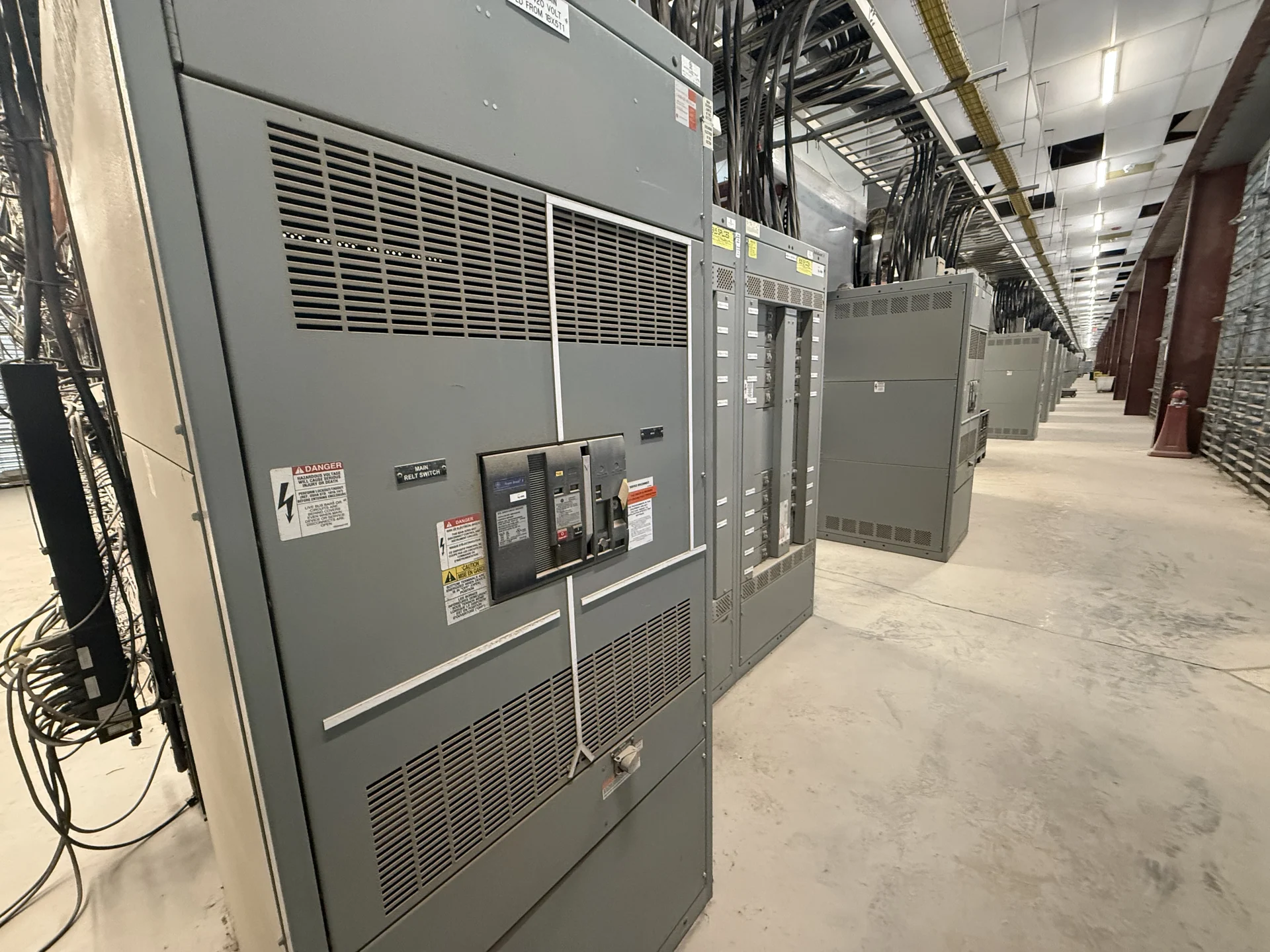
Nebraska switchgear projects often place distribution equipment outdoors, where the design must account for the actual site rather than a generic enclosure assumption. Start with the system one-line diagram, nominal voltage, phase arrangement, grounding method, continuous current, available fault current, and intended feeder topology. Then document the pad location, finished grade, drainage, access route, clearances, cable trench or duct-bank arrangement, and nearby structures. Wind, precipitation, temperature swings, dust, and seasonal ground conditions may affect enclosure selection, foundation details, door operation, and maintenance access. A manufacturer can use these inputs to develop new pad-mounted switchgear custom to the electrical and physical requirements of the project.
Define Switching Duty Before Selecting Equipment
The switching sequence is as important as the cabinet footprint. Identify whether the pad-mounted lineup will sectionalize a feeder, isolate a transformer, provide a loop arrangement, or support another project-defined operating scheme. Specify normal and alternate source paths, which devices must open under load, whether fuses or circuit breakers are contemplated, and how operators will determine equipment status. Protection and coordination studies should establish interrupting or fault-duty requirements and appropriate device settings; those values should not be guessed from the location alone. Interlocks, keying, visible isolation, and access controls also deserve review with the engineer and utility or owner responsible for operating the system.
Match the Enclosure to Nebraska Exposure
Outdoor equipment should be described by its exposure and maintenance environment, not simply labeled weatherproof. Confirm the enclosure type, materials, finish, corrosion considerations, drainage provisions, door and latch arrangement, ventilation needs, and any separation between power compartments and operating areas required by the design. The civil team should coordinate the equipment pad, anchor points, cable bends, barriers, and working space with the electrical layout. If snow accumulation, blowing dust, standing water, or restricted access is possible at the proposed location, record those conditions for engineering review. The final enclosure and installation details must follow project specifications and applicable local requirements.
Coordinate Cable Entry and Field Interfaces
Cable entry frequently determines whether a pad-mounted arrangement can be installed without field changes. Provide conductor type and size, number of circuits, termination style, phase spacing, bending radius, shield or grounding details where applicable, and the direction from which each cable approaches the equipment. Show conduit locations, spare pathways, transformer or feeder interfaces, and the relationship between the pad and finished grade. Include control, metering, communications, and auxiliary wiring only when they are part of the defined scope. Dimensioned drawings and a reviewed cable schedule let the manufacturer align compartments, barriers, lugs, supports, and access points before fabrication rather than relying on assumptions at the jobsite.
Buy New Switchgear Directly From the Manufacturer
When a Nebraska owner, contractor, utility project team, or engineer needs new equipment, a useful quote request should identify the project location, equipment function, one-line diagram, ratings, enclosure environment, switching sequence, cable schedule, site dimensions, and required drawings. Also state the desired component preferences, testing scope, documentation, freight destination, unloading constraints, and who will review submittals. Switchgear Builders manufactures new electrical switchgear in the United States, builds custom equipment to specification, uses American components, and supplies projects with nationwide shipping. Project engineering should confirm the configuration, component suitability, applicable standards, and delivery terms for the specific order.
Review Delivery, Installation, and Acceptance Inputs
A complete plan continues beyond the electrical drawing. Establish shipping sections, approximate weights, lifting points, center-of-gravity information, truck access, receiving responsibility, storage protection, and the route from unloading to the pad. Before shipment, align approved drawings with foundation dimensions, conduit stub-ups, phase identification, operating clearances, and the installer’s termination plan. At receipt, the qualified project team should inspect packaging and equipment condition, record any discrepancies, and preserve documentation for installation and commissioning. If the specification invokes UL 891 or another standard, confirm its applicability, required construction, and any project-specific listing or evidence during engineering review rather than assuming a universal result.