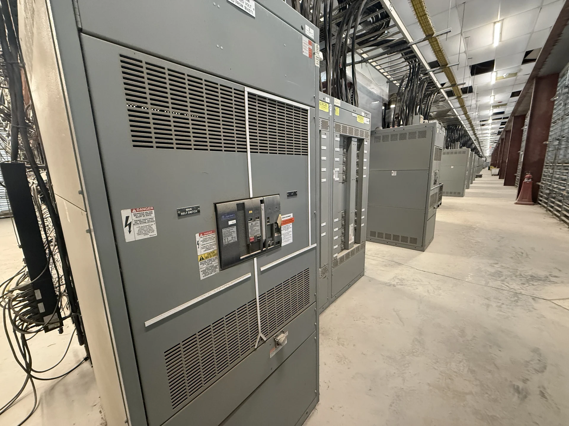
Start With the Expansion Load Map
A facility expansion in Milwaukee, Wisconsin should begin with a clear picture of what the new electrical feeders must serve and how those loads relate to the existing distribution system. Gather the present one-line diagram, service information, transformer data, feeder schedules, calculated demand, motor or process loads, and anticipated future capacity. Separate confirmed loads from allowances for growth, because that distinction affects bus capacity, protective-device selection, physical lineup space, and the coordination study. A manufacturer can use this information to develop new switchgear custom to the project rather than treating a generic catalog arrangement as a finished design. For a phased build, mark which existing feeders will remain energized during construction and which new loads need dedicated sections, so temporary connections do not obscure the final operating plan.
Confirm Interfaces With Existing Equipment
Expansion equipment must connect predictably to the distribution equipment already serving the facility. Document the existing lineup manufacturer and identification, bus arrangement, incoming conductor details, feeder locations, grounding method, control voltages, metering interfaces, and available fault-current information where those records exist. Field verification may be necessary when drawings do not match the installed arrangement. The design team should also identify whether the new section is electrically adjacent, remotely connected, or supplied through a separate source. These interface details help define dimensions, connection points, barriers, controls, and commissioning responsibilities before a custom switchgear quotation is prepared. Record cable insulation type, termination orientation, and phase rotation at the interface; these details can prevent a physically correct lineup from creating difficult field rework during tie-in.
Plan Outage Windows and Cutover Work
A new feeder project is also an operating-plan project. List the loads that cannot tolerate interruption, the systems that can be temporarily isolated, and the sequence required for demolition, installation, cable termination, testing, and energization. Coordinate the proposed outage window with the facility owner, electrical engineer, installing contractor, utility or service representative when applicable, and qualified safety personnel. A phased lineup, temporary source, or separately scheduled tie-in may be considered only after engineering review and site planning. The manufacturer needs the intended switching sequence and interlock requirements so the equipment design reflects how the expansion will actually be integrated. Include lockout boundaries, test points, and responsibility for proving dead before work begins; an outage schedule is incomplete if switching authority and return-to-service checks remain undefined.
Reserve and Verify Physical Space
Electrical capacity alone does not make an expansion lineup workable. Measure the proposed room and delivery route, then compare those dimensions with equipment sections, working clearances, cable-bending space, ventilation needs, access doors, structural openings, and lifting or handling constraints. Check whether the floor, housekeeping pad, wall penetrations, and overhead path can support the planned installation. Future feeder sections may be valuable, but spare space must be reconciled with the real footprint and maintenance access. Supplying a marked-up plan, photographs, and confirmed dimensions gives a U.S. manufacturer better information for a build custom to the Milwaukee project site.
Define Ratings, Protection, and Documentation
The equipment inquiry should state system voltage, frequency, phase and wire arrangement, continuous current requirements, available fault current, grounding method, environmental conditions, enclosure location, feeder quantity, protective-device preferences, metering, controls, and communication needs. The engineer should establish protection settings and coordination objectives rather than leaving them implicit in a product description. Specify the drawings, bills of material, wiring diagrams, nameplate information, inspection records, and functional checks expected with the equipment package. If UL 891 may apply, confirm its relevance, construction requirements, and any project-specific listing or verification before final design; applicability is not automatic for every assembly. For expansion feeders serving variable-speed drives or large motors, provide starting characteristics and harmonic concerns early, because they can influence breaker settings, bus arrangement, and monitoring provisions.
Request a Project-Specific Manufacturing Quote
When the scope is assembled, send the manufacturer the one-line diagram, load schedule, existing-equipment information, room layout, site conditions, desired feeder arrangement, control narrative, documentation requirements, destination, and requested commercial inclusions. Switchgear Builders manufactures new electrical switchgear in the United States, builds custom equipment to specification with American components, and supplies projects with nationwide shipping. Engineering review should establish the final scope, including assumptions, exclusions, approval drawings, testing expectations, freight responsibilities, receiving access, and project-specific schedule and availability.