When a Retrofit Is the Right Project
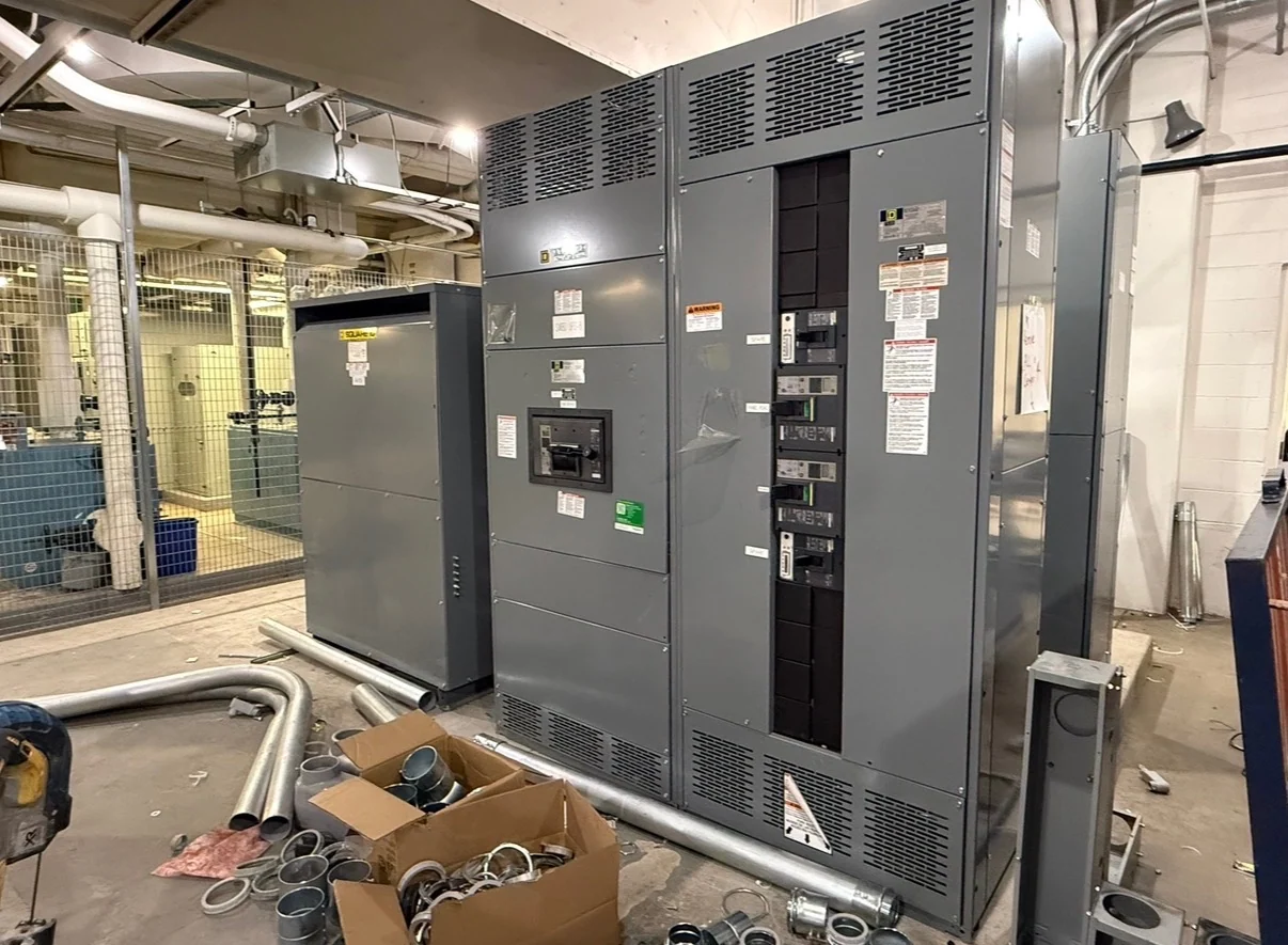
A switchgear retrofit modifies an operating distribution arrangement while preserving selected interfaces, rather than treating every project as a simple replacement. It can address obsolete protective devices, changed loads, damaged compartments, control revisions, or a need for new equipment that fits an established lineup. The decision starts with a qualified assessment of the present assembly, the electrical objective, and the installation constraints. Compare the retrofit option with a complete new lineup by considering outage duration, room access, feeder continuity, available drawings, future expansion, and the amount of field work required. Switchgear Builders manufactures new retrofit equipment in the United States, custom to specification, using American components and offering nationwide shipping; the final scope remains specific to the documented project.
Document the Existing Assembly Before Design
Useful retrofit engineering depends on reliable information about the existing switchgear. Gather the nameplate data, one-line diagram, lineup dimensions, compartment drawings, bus and cable locations, available fault current, voltage, frequency, grounding method, and protective-device information. Photographs should show doors, barriers, terminals, interlocks, wiring routes, and signs of heat or mechanical damage, with measurements tied to identifiable locations. A manufacturer can then compare the requested new assembly with field conditions instead of assuming that a familiar model or footprint will fit.
Check Compatibility at Every Interface
Compatibility is more than matching a breaker name or current rating. A retrofit review should examine primary stabs, bus alignment, phase spacing, shutters, racking geometry, secondary plugs, control voltage, terminal assignments, instrument transformers, interlocks, arc barriers, cable bending space, and door clearances. The proposed device must also suit the system voltage, continuous load, interrupting duty, and protection scheme. Review whether existing relays, meters, trip units, and auxiliary contacts remain part of the control philosophy or need new interfaces. Where dimensions or legacy drawings are uncertain, field verification and engineering review should resolve the uncertainty before fabrication.
Engineer the New Retrofit Assembly
Once the interfaces and electrical requirements are defined, the manufacturer can develop a project-specific design for the new retrofit components or sections. Typical design work may include enclosure modifications, mounting structures, bus connections, control wiring, terminal identification, metering provisions, and interlock logic, depending on the requested scope. Drawings should identify what remains, what is replaced, and how installers connect the new work. If the project involves a switchboard or a UL 891 question, the applicable equipment standard, construction requirements, and any listing needs must be confirmed for that specific design.
Plan Safety, Outage, and Installation Interfaces
A retrofit plan should define who isolates, verifies, removes, installs, tests, and returns the equipment to service. The electrical contractor and facility team need an agreed outage sequence, access route, lifting method, temporary power approach where relevant, and responsibility for field terminations. Existing equipment condition can affect disassembly and may require additional engineering decisions, but no condition should be assumed from photographs alone. Installation documents should identify torque requirements, wire labels, mechanical checks, grounding connections, and any site-specific safety procedures supplied by the responsible professionals.
Test and Close Out the Retrofit
Testing should follow an approved, project-specific plan that matches the modified circuits and the equipment furnished. Depending on scope, checks may include visual and dimensional inspection, wiring continuity, insulation resistance, control-function verification, interlock operation, phase identification, device settings, and primary-circuit tests performed with suitable procedures and instruments. Results should be recorded with drawing revisions, component data, and punch-list resolution. Before requesting a quote, provide the intended acceptance criteria and witness expectations so the manufacturer, engineer, and installer can coordinate a useful closeout package.