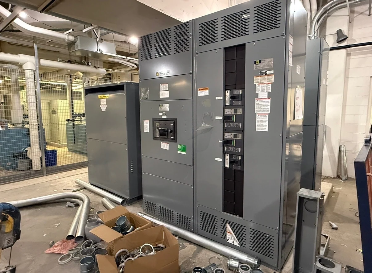
What a Metering Switchboard Must Accommodate
A metering switchboard combines distribution functions with provisions for measuring electrical energy at a defined service or feeder interface. The design must separate the utility's metering requirements from the owner's monitoring goals, because those needs may involve different instruments, compartments, wiring, and access rules. Begin with the one-line diagram, nominal voltage, phase and wire arrangement, service or feeder designation, continuous current, available fault current, grounding method, and the devices that will occupy the lineup. A manufacturer can then build new equipment custom to the approved electrical and physical requirements rather than treating metering as an interchangeable accessory.
Coordinate Utility Metering Requirements Early
Utility requirements can determine cabinet sections, instrument-transformer placement, meter sockets or compartments, sealing provisions, test switches, conductor routing, and the boundary between utility-controlled and customer-controlled spaces. Those details vary by serving utility and project arrangement, so the electrical engineer or project team should obtain the current utility service manual and identify who reviews drawings before fabrication. Include the service address, utility contact or submission path, metering point, service conductors, transformer ownership, and any required metering diagram in the quote package. Manufacturer review can confirm whether the requested switchboard layout reflects those project-specific inputs, but it should not substitute for utility approval.
Choose the Measurement Architecture
Metering switchboards may be arranged for revenue-related utility measurement, customer submeters, power-quality instruments, or a combination of functions, each with different accuracy, isolation, communication, and maintenance considerations. Decide whether measurement is direct-connected or transformer-connected, what circuits require separate readings, and whether current transformers and potential transformers need dedicated compartments or terminal access. Specify ratios, accuracy classes, burden requirements, polarity markings, shorting or test provisions, meter types, and communication interfaces only when they are established by the engineer, utility, or owner. A clear measurement schedule helps prevent a physically attractive lineup from lacking the connections needed during commissioning.
Plan the Switchboard Layout Around Access
Physical arrangement affects installation, inspection, meter reading, troubleshooting, and future device replacement. Define the overall lineup footprint, section sequence, cable entry, bus orientation, termination space, door swings, removable covers, equipment height, and the movement route into the electrical room. Utility-accessible metering areas may need controlled separation from sections reserved for qualified facility personnel; that boundary should be shown on drawings instead of inferred from labels. Also coordinate working clearances, ventilation, housekeeping pads, conduit paths, and wall or floor interfaces with the installer. A detailed elevation and plan view lets the manufacturer identify conflicts before fabrication and supports a more predictable receiving and placement process.
Define Protection and Distribution Coordination
Metering does not replace protection design. The main and feeder devices still require ratings and settings appropriate to calculated load, available fault current, conductor ampacity, selective coordination objectives where applicable, and the operating sequence of the distribution system. Identify main, feeder, and tie devices; bus continuous-current requirements; short-circuit duty; neutral and grounding conductors; surge protection if specified; and any control or indication circuits. Metering conductors should be routed and terminated so they remain identifiable and maintain the intended separation from power circuits. The final arrangement should be reviewed against the approved one-line diagram and coordination study by the responsible electrical professionals.
Prepare a Complete Manufacturer Quote Request
For a useful custom switchgear quote, send the one-line diagram, metering schematic, equipment schedule, site and room dimensions, utility criteria, service voltage and frequency, phase and wire configuration, current and fault-duty requirements, enclosure environment, cable-entry direction, required devices, communications needs, drawing standards, inspection or witness expectations, and shipping destination. State which components must be American-made and identify any owner, engineer, or utility submittal milestones. Switchgear Builders manufactures new electrical switchgear in the United States, uses American components, and can coordinate nationwide shipping; project-specific configuration, documentation, commercial terms, and transit details must be confirmed for the order.