A Compact Map of the Power System
A one-line diagram, also called a single-line diagram, is a simplified drawing of an electrical distribution system. Instead of showing every conductor separately, it uses one line and standardized symbols to represent three-phase or other multi-conductor circuits. The drawing identifies how power moves from an incoming utility service, generator, transformer, or other source through switchgear and downstream equipment. It is not a wiring diagram or installation detail; it is a system-level map that lets engineers, contractors, owners, and manufacturers discuss the same electrical arrangement. For a new custom switchgear inquiry, this diagram is often the starting point for defining the lineup, devices, bus sections, feeders, and control relationships.
Sources, Buses, and Feeders
The source portion of a one-line diagram shows where electrical energy enters the system and may identify multiple normal or alternate sources. A bus is the common conductive section that receives and distributes power inside an assembly, while feeders carry power from that bus toward transformers, panelboards, motor control centers, buildings, or process loads. The drawing can show a main bus, separate bus sections, and a tie between sections, but the symbol alone does not determine the final physical arrangement. A manufacturer needs the intended operating sequence, source relationships, grounding approach, phase and frequency, and connection points before converting the concept into equipment drawings.
Protective Devices and System Duties
Protective devices on the diagram indicate how portions of the distribution system can be disconnected or protected during an electrical fault or overload. Depending on the project, symbols may represent circuit breakers, fusible switches, relays, instrument transformers, disconnecting means, or other specified devices. The one-line should be reviewed alongside calculated load current, available fault current, voltage class, continuous-current needs, and protective-device coordination information. A symbol is not a complete rating specification, and a one-line cannot by itself confirm interrupting capability, short-circuit withstand, enclosure selection, or protection settings. Those details must be established through engineering review and the project specification.
Reading the Drawing Before Requesting a Quote
Before requesting a manufacturer quote, check whether the one-line clearly identifies each source, main device, tie or transfer function, bus section, feeder destination, and metering or control requirement. Compare the drawing with the load schedule and site information so that omissions become questions rather than assumptions. Add the desired equipment location, indoor or outdoor exposure, available working space, cable-entry direction, approximate dimensions, utility requirements, and any installation constraints. If a project calls for a particular standard or UL 891 consideration, state that requirement for review; applicability and any project-specific listing or verification must be confirmed rather than inferred from the diagram.
From One-Line Concept to Custom Equipment
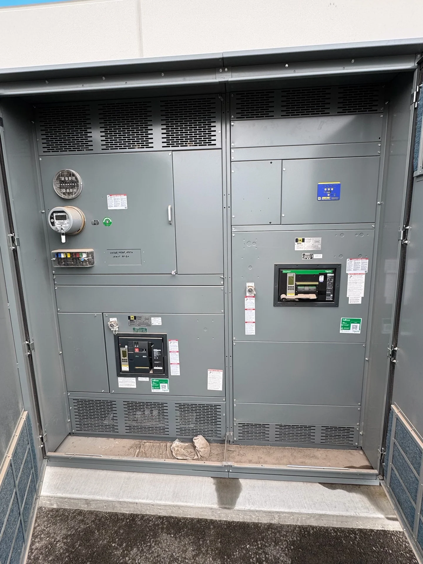
A manufacturer uses the one-line as an electrical reference while developing a physical and functional equipment package. The design process may translate each source and feeder into compartments, bus sections, protective devices, terminals, metering, and control wiring, subject to the specified ratings and available components. This is where conflicts often surface: a feeder may require a different cable space, a tie may need a defined interlock sequence, or a proposed device may not suit the stated fault duty. Switchgear Builders builds new custom electrical switchgear in the United States with American components and can coordinate the one-line, equipment layout, control requirements, and documentation for a project-specific quotation.
Revisions, Review, and Delivery Coordination
Treat the one-line as a controlled project document rather than a sketch that stops changing after the first conversation. Revisions to source capacity, feeder count, protection, metering, or operating sequence can affect enclosure space, bus design, device selection, drawings, and installation interfaces. Identify the drawing revision and the engineer responsible for approval, then coordinate submittal comments before fabrication proceeds. Once the scope is defined, nationwide shipping can be planned around shipping splits, lifting points, packaging, destination access, and receiving responsibilities. The manufacturer should confirm project-specific availability, shipping details, and documentation rather than relying on generic assumptions.