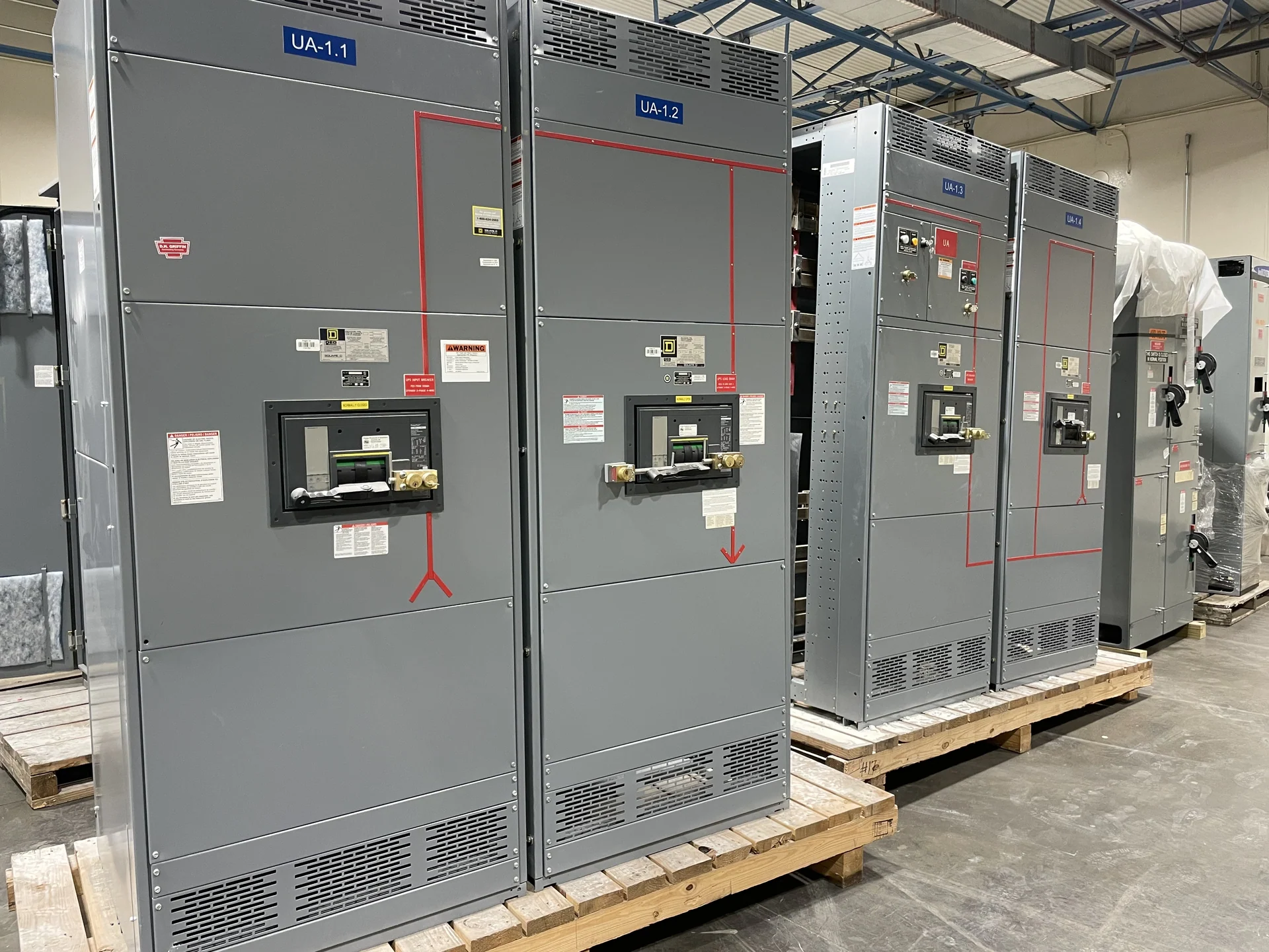
What a One-Line Diagram Shows
A one-line diagram is a simplified drawing of an electrical power distribution system. Instead of showing every conductor separately, it uses a single line to represent a circuit path and symbols to identify sources, transformers, switchgear, switchboards, circuit breakers, disconnects, buses, feeders, and loads. The drawing communicates how power is arranged and controlled without reproducing the physical wiring in full detail. For a new switchgear project, it gives the manufacturer a common starting point for understanding the intended distribution topology before enclosure dimensions, device details, and connection points are finalized.
Why Engineers Use This Drawing
Engineers use a one-line diagram to discuss system architecture, trace power paths, assign protective devices, and identify interfaces between utility service, generation, transformers, distribution sections, and downstream loads. It can support fault-duty review, protective-device coordination, grounding discussions, metering planning, and source-transfer sequences, although the drawing itself does not replace those calculations or a complete design package. When requesting custom switchgear, provide the current project drawing together with the design basis so questions about scope are answered before fabrication documents are prepared.
Information to Identify Clearly
A useful one-line diagram identifies each source and bus, the direction of power flow, feeder destinations, nominal voltage, phase and wire arrangement where applicable, transformer relationships, protective-device types, and major load groupings. It should distinguish normal and alternate sources when a transfer or tie arrangement is involved. Notes should call out grounding method, metering points, control interfaces, future provisions, and any required operating sequence. Ratings and settings belong in coordinated schedules or specifications as well, but the diagram should reference them consistently so the equipment builder is not forced to infer critical requirements.
Using the Diagram for a Custom Quote
For a manufacturer quote, the one-line diagram is most effective when paired with the requested equipment type, system voltage, continuous-current needs, available fault current, enclosure environment, dimensions or room constraints, cable-entry direction, and documentation expectations. Mark the portion included in the new lineup and identify interfaces that remain outside the equipment scope. A quotation request should also explain whether the arrangement is fixed-mounted or drawout, how main and tie devices are intended to operate, and which control, indication, or communications functions require engineering review.
Reading Symbols Without Guessing
Symbols on a one-line diagram are shorthand, not universal permission to assume a particular component or rating. A breaker symbol indicates a switching and protection function, but its interrupting capability, trip unit, mounting arrangement, and settings must come from the project specification. A transformer symbol shows an electrical relationship, not every connection detail. Likewise, a tie line may indicate an operating option whose interlocks and controls require a written sequence. Ask the engineer of record to clarify ambiguous symbols, abbreviations, and notes before a new American-built switchgear assembly is released for design.
Review Before Release and Shipment
Treat the one-line diagram as a controlled project document. Compare its source, bus, feeder, and protective-device information with panel schedules, load calculations, cable schedules, physical layouts, and the switchgear submittal. Revisions should be dated and clearly identified so the manufacturer, engineer, contractor, and owner are working from the same arrangement. Switchgear Builders manufactures custom new electrical switchgear in the United States with American components and can coordinate the equipment scope and nationwide shipping around project information supplied for review. Any applicable standard, including UL 891, must be evaluated for the specific assembly and confirmed as part of the project rather than assumed from the drawing alone.