Start With the Electrical Operating Intent
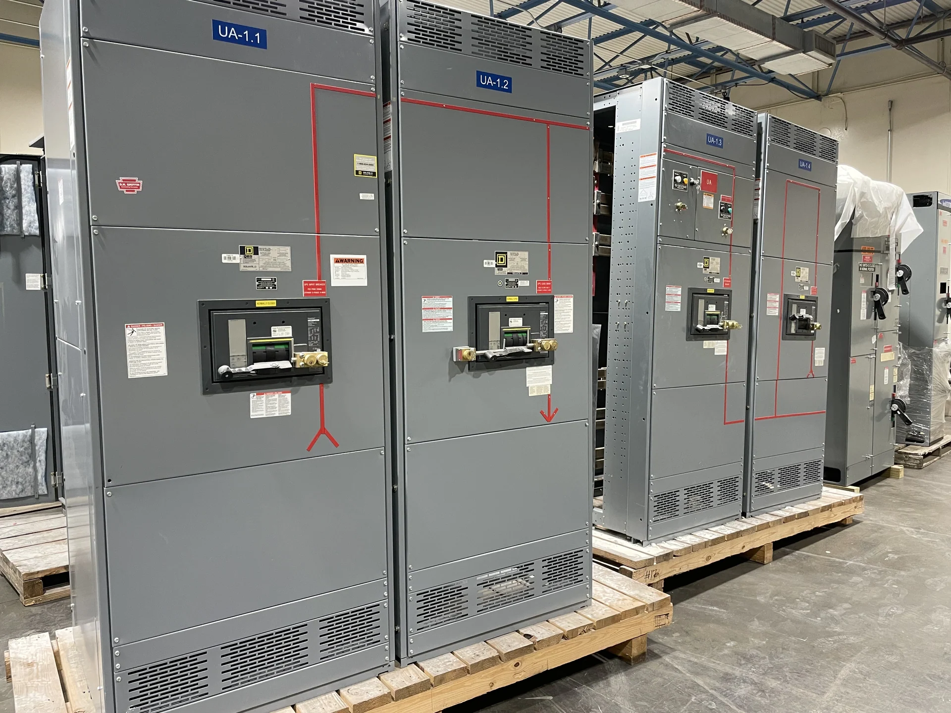
A custom switchgear control scheme should begin with the way the distribution system is meant to operate, not with a preferred panel arrangement. Define each source, bus section, feeder, protective device, and controlled load, then describe normal, abnormal, maintenance, and restoration states in plain language. A one-line diagram, source information, grounding approach, load priorities, and operating constraints give the manufacturer a workable design basis. Switchgear Builders manufactures new electrical switchgear in the United States, custom to project specifications, using American components and supplying equipment with nationwide shipping coordination. Include the intended operator actions and the conditions that indicate a command was accepted, rejected, or interrupted. That detail helps distinguish a control requirement from a protection function and exposes unresolved questions early in design review.
Translate the Sequence Into Control Logic
The operating sequence should state what must happen, what must never happen, and which conditions permit a transition. For example, a source breaker may close only when its disconnect position, voltage condition, synchronism requirement, and associated bus status are appropriate; those conditions are hypothetical until an engineer confirms the actual application. Document permissives, trips, alarms, timers, reset behavior, and loss-of-control-power responses separately. This turns a narrative request into a reviewable control scheme rather than leaving critical assumptions hidden in wiring details. A written matrix can map each initiating event to the expected breaker position, alarm, indication, and reset action. It also gives the project team a common reference when electrical drawings, controls narratives, and installation responsibilities are reviewed.
Design Source Interlocks Around Safe States
Source interlocks coordinate mains, ties, alternate sources, and grounding or bypass equipment so an operating action follows the approved sequence. The design team should identify whether sources may operate in parallel, whether a break-before-make transition is required, and what electrical or mechanical conditions block an unsafe command. Interlock logic may involve auxiliary contacts, key interlocks, relays, programmable controls, or a combination, but the selection depends on the project sequence and equipment architecture. Every permissive and blocking condition should be traceable to a drawing or written requirement. Interlocks should be evaluated for loss of auxiliary power, welded contacts, failed indication, and a local-versus-remote control selection. The final arrangement should make the permitted operating state understandable to qualified personnel and consistent with the approved design.
Coordinate Controls With Protection and Interfaces
Control decisions cannot be separated from protection settings, breaker capabilities, metering, generator controls, transfer equipment, or building automation interfaces. Identify which device initiates a trip, which signal reports status, whether a remote command is momentary or maintained, and how loss of communications affects operation. Engineers should review time coordination, available fault current, short-circuit duties, and utility requirements as applicable. A custom manufacturer can use this information to align terminal blocks, control power, labeling, wiring segregation, and interface points with the project documentation. Confirm which signals remain available during a trip or communications failure, and identify any required hardwired path separately from network data. These distinctions affect control-power sizing, terminal allocation, troubleshooting, and the boundaries between manufacturer and installer work.
Make Drawings and Testing Match the Scheme
A useful control package includes a sequence of operations, elementary diagrams, wiring diagrams, point lists, terminal schedules, device designations, and clearly defined revision responsibilities. During review, walk through normal transfer, failed-source response, manual operation, emergency stop, alarm acknowledgment, and return-to-normal behavior using the actual proposed signals. Factory inspection and functional checks should follow acceptance criteria agreed for the project; they do not replace field commissioning, protection studies, or the qualified professional review required for the installation. Record the revision of the sequence used for inspection so a later drawing change does not silently alter the test basis. Any witnessed demonstration should use agreed scenarios and retain results that identify the device, input, expected response, and observed response.
Prepare a Precise Custom-Scheme Inquiry
For a useful quote on custom electrical distribution equipment, provide the project location, one-line diagram, system voltage and frequency, phase and wire configuration, continuous-current requirements, available fault current, enclosure conditions, lineup dimensions, source details, control voltage, desired operating sequence, interlock philosophy, communications needs, drawings, testing expectations, and shipping constraints. Identify open decisions instead of guessing them. The manufacturer can then clarify scope, component choices, documentation, and project-specific requirements before preparing new switchgear for purchase and delivery. State whether the shipment is arranged as one lineup or multiple sections, and coordinate receiving, lifting, placement, field connections, and startup responsibilities. Clear logistics information reduces the chance that a sound control design is undermined by an unresolved installation interface.