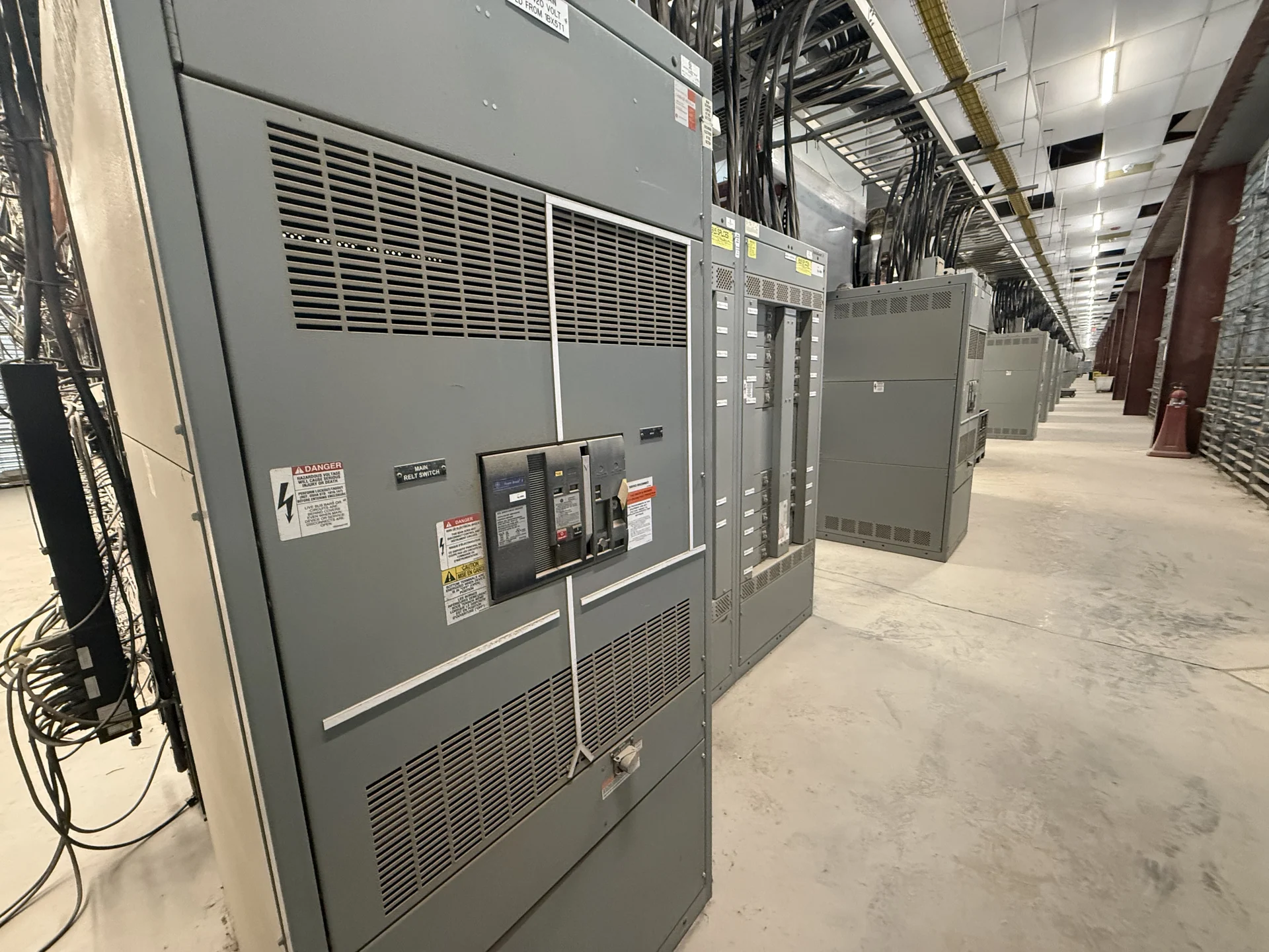
Start with the electrical design basis
Custom switchgear building begins with a clear electrical design basis rather than a preferred enclosure shape. The project team should provide the one-line diagram, system voltage, phase and frequency, grounding method, continuous current, available fault current, feeder destinations, protective-device duties, and operating sequence. These inputs establish what the new assembly must do and reveal assumptions that need engineering review before fabrication. Switchgear Builders manufactures new electrical switchgear in the United States, custom to specification, using American components and supporting nationwide shipping.
Translate ratings into a workable lineup
Ratings become practical only when they are connected to a defined lineup. A manufacturer can organize mains, ties, feeders, bus sections, metering, and control compartments around the specified electrical arrangement, while accounting for cable entry, conductor bending space, termination points, and access for installation. Current and voltage values should be checked against calculated loads, fault studies, protective coordination, and the equipment class selected by the engineer. Future capacity may influence section size, spare provisions, and bus arrangement, but it should be identified explicitly instead of assumed. The specification should distinguish required capacity from optional expansion, because unused spaces, spare devices, and future feeder provisions affect both layout and coordination.
Coordinate dimensions and installation interfaces
Physical coordination is as important as the schematic. Useful design information includes the available room footprint, shipping path, door and ceiling clearances, floor conditions, anchorage points, cable trench or overhead entry, adjacent equipment, ventilation needs, and required working space. The custom switchgear builder can divide a lineup into shipping sections and identify lifting provisions after weights and center-of-gravity information are developed. Confirming these interfaces early reduces the risk that a correctly rated assembly cannot pass through the building or connect to field-installed conductors. Include the planned direction of cable pull, termination hardware, access-panel swing, and route for moving each section; those details can change section boundaries even when the electrical diagram stays unchanged.
Define controls, interlocks, and documentation
Control requirements should be written as operating behavior, not just a list of devices. Describe source-selection logic, main and tie interlocking, breaker status, permissives, alarms, remote signals, metering points, and the normal and alternate operating sequences. The design package can then identify control voltage, terminal blocks, wire labels, communication interfaces, and segregation between power and control wiring. A complete submittal should also state drawing formats, revision responsibilities, device data, wiring diagrams, inspection points, and the records required for installation and commissioning.
Build, inspect, and prepare the new equipment
After design approval, fabrication and assembly bring the specified enclosure, bus conductors, protective devices, metering, and controls together as one coordinated product. Manufacturing checks may include dimensions, hardware, conductor identification, clearances, torque documentation, wiring continuity, insulation-related checks where applicable, and functional operation against the agreed test plan. Acceptance criteria must be defined for the project; no generic statement substitutes for the engineer's requirements or the applicable standards. If UL 891 is relevant, its applicability and any project-specific listing requirements must be confirmed before the order is finalized.
Plan delivery and field completion
A custom switchgear project is not complete when the lineup leaves manufacturing. The purchase package should identify shipping sections, destination details, receiving responsibilities, lifting equipment, storage conditions, field-assembly steps, and the documents that accompany the equipment. Nationwide shipping can be coordinated for U.S. projects, with transit estimates and freight terms confirmed for the specific order rather than promised in advance. The installing team should compare received sections with approved drawings, inspect for transport damage, verify interfaces, and complete installation and site testing under qualified supervision. Clarify who supplies field lugs, transition hardware, control power, raceways, and final terminations so the installer can resolve scope boundaries before the outage or energization plan is set.