Map the Utility-to-UPS Power Path
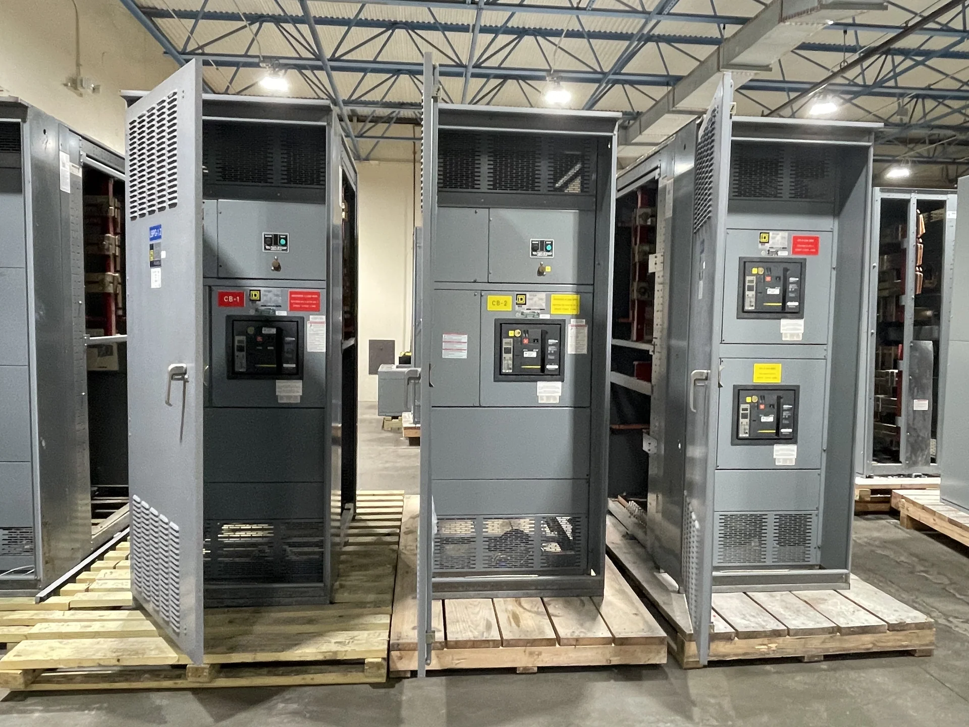
Utility-to-UPS distribution for data centers should begin with a clear one-line map, not a catalog label. Identify the incoming service, service disconnecting means, main distribution equipment, feeders, transformers, bypass arrangements, and UPS inputs in their actual operating order. Then distinguish equipment that belongs to the utility interface from equipment controlled by the facility. This sequence helps the design team define where switchgear must switch, protect, meter, isolate, or provide a tie. Switchgear Builders manufactures new electrical switchgear in the United States to project specifications, using American components and shipping completed assemblies nationwide.
Define Source and Feeder Requirements
The utility source information should be translated into equipment requirements before a custom switchgear quote is prepared. Provide nominal voltage, phase and wire arrangement, grounding method, frequency, available fault current, continuous load, prospective expansion, and the utility's service-interface requirements when available. For each feeder serving a UPS or related transformer, identify conductor entry, termination space, protective-device type, interrupting duty, metering, and isolation needs. A data center distribution plan may have several electrically separate paths, so label normal, alternate, maintenance-bypass, and emergency interfaces explicitly rather than assuming identical arrangements. Final ratings and coordination require qualified engineering review.
Coordinate UPS and Transformer Interfaces
UPS equipment does not eliminate the need to coordinate upstream switchgear with transformers, bypass sources, and downstream distribution. Confirm transformer impedance, inrush expectations, secondary arrangement, grounding connections, feeder protection, and the UPS manufacturer's input and bypass requirements. Where a transformer supplies a UPS input, the switchgear design should show how the feeder is isolated and how protective devices relate to the transformer and downstream equipment. If a static bypass or maintenance bypass is part of the system, document its source, interlocking, and operating sequence. These details affect enclosure layout, control wiring, terminations, and the drawings included with a custom build.
Plan Redundancy Without Assuming Identical Paths
Many data centers divide critical power among separate distribution paths, but the correct architecture depends on the facility's topology and operating rules. Compare independent utility or generator-fed lineups, main-tie-main arrangements, dual-cord UPS inputs, and maintenance-bypass provisions against the actual one-line diagram. Ask whether a bus tie is normally open or closed, which source may energize it, what interlocks prevent an unintended parallel condition, and how operators verify source status. Separate physical rooms, cable routes, and maintenance boundaries may also influence lineup sections. Switchgear should document the intended sequence rather than relying on a generic redundancy label.
Coordinate Physical Installation and Documentation
A technically correct electrical arrangement can still fail at installation if physical interfaces are left vague. Supply room dimensions, working clearances, equipment movement paths, floor elevations, cable-trench details, entry direction, conduit locations, lifting needs, and heat or ventilation constraints for review. Identify which sections must ship together and which can be separated for access, transportation, or rigging. A useful submittal package can include the one-line diagram, elevation, plan view, device schedule, terminal information, control schematic, nameplate data, and project-defined inspection or test records. Confirm document responsibility and approval milestones with the engineer, contractor, and owner.
Prepare a Manufacturer Quote Request
For a focused quote request, send the current one-line diagram, load and fault-study inputs, utility comments, UPS and transformer data, source and bypass sequence, physical constraints, environmental conditions, preferred protective devices, metering needs, control-voltage requirements, and documentation expectations. State whether the project calls for indoor or outdoor construction and identify any project standard that governs enclosure, testing, or acceptance. If UL 891 may apply to a switchboard portion, treat applicability and any project-specific listing or capability as an item to confirm rather than an assumption. Switchgear Builders can review a new custom scope for American-built supply and coordinate nationwide shipment details for the specified destination.