Start with the Feeder System Model
Feeder distribution for oil and gas facilities begins with a clear model of how power moves from each source to process loads, buildings, motor control centers, and supporting systems. Gather the one-line diagram, nominal voltage, phase and frequency, grounding method, continuous load, motor-starting demand, available fault current, and planned expansion. Identify whether a feeder supplies pumps, compressors, heaters, instrumentation, emergency loads, or a mixture of load types. Those details shape the switchgear applications, bus arrangement, protective devices, cable terminations, and enclosure requirements. A qualified electrical engineer should reconcile the design with site-area classifications, utility conditions, and applicable project requirements before equipment is released for manufacture.
Match Ratings to Actual Electrical Duty
Equipment ratings should describe the duty the feeder can actually encounter, not merely the connected load shown on a preliminary schedule. Review system voltage and equipment voltage class separately, then establish continuous-current ratings for mains, buses, and individual feeders. Compare each protective device interrupting rating with available fault current at its installation point, considering source changes, transformers, generators, and motor contribution where applicable. For oil and gas electrical distribution, also examine short-circuit withstand, insulation coordination, phase spacing, grounding, and the effects of long cable runs. Rating selections remain project-specific: final values depend on the study, governing specifications, and the exact switchgear configuration.
Protection coordination deserves its own review because process continuity and selective fault clearing can pull design decisions in different directions. Collect time-current curves, relay functions, breaker trip units, fuse data where applicable, and upstream utility or generator settings. An engineer can then evaluate feeder protection against transformer damage limits, motor starting, arc-flash objectives, and downstream device selectivity. A custom switchgear builder can translate the approved settings and operating sequence into device compartments, control wiring, labeling, and documentation. Settings should not be guessed from a typical oilfield arrangement; they belong to the reviewed electrical study and commissioning plan.
Account for Process Loads and Site Conditions
Oil and gas facilities often combine large motors, variable process loads, control systems, outdoor equipment, and areas with defined hazardous-location requirements. The feeder package should identify the environmental exposure at the installation point, including moisture, dust, corrosive agents, temperature range, solar exposure, elevation, and washdown or drainage conditions. Confirm enclosure construction, cable-entry methods, space heaters or ventilation if specified, and material or coating requirements through the project documents. Area classification and equipment-location decisions require qualified engineering review; a general-purpose enclosure description cannot establish suitability for a particular classified area or process zone.
Define a Buildable Custom Configuration
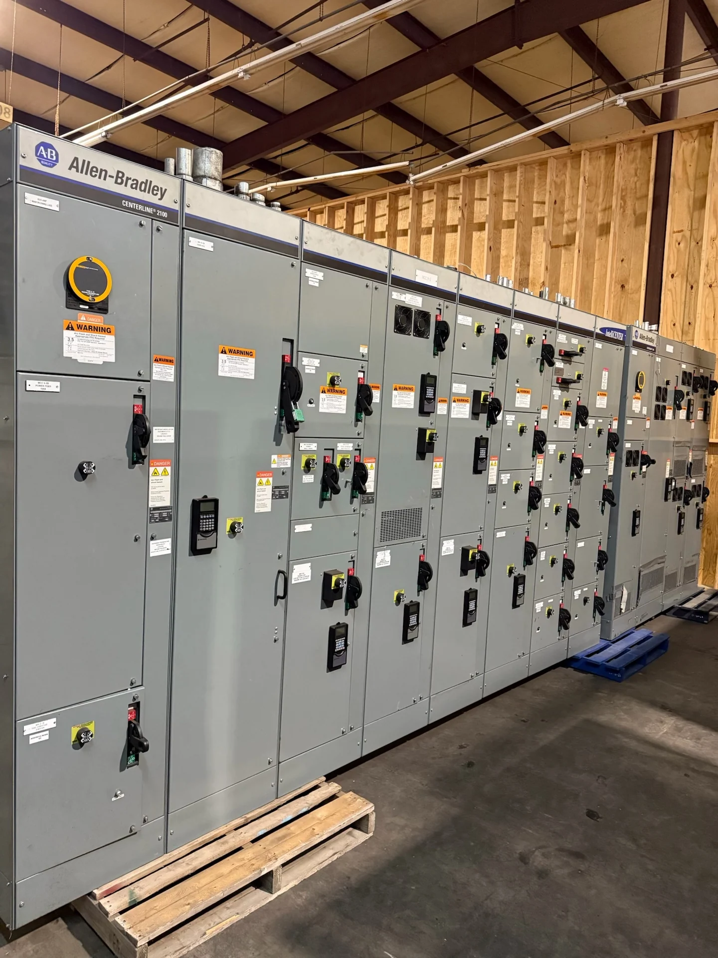
A useful custom switchgear inquiry gives the manufacturer enough information to build around the real feeder interfaces. Include approved one-lines, load schedules, equipment elevations, bus and cable entry preferences, incoming and outgoing conductor sizes, termination space, control voltage, metering points, communications needs, interlocks, and the required operating sequence. Show whether feeders are fixed or drawout, how isolation is intended to work, and where maintenance access must be preserved. Switchgear Builders manufactures new electrical switchgear in the United States, custom to specification, using American components and supporting nationwide shipping; the final build remains dependent on the project documents and agreed scope.
Coordinate Installation and Documentation
Feeder distribution succeeds only when the lineup can be received, moved, installed, terminated, tested, and integrated without unresolved interface questions. Coordinate shipping splits, section weights, lifting provisions, floor or foundation details, door swing, working space, cable bending room, grounding connections, and the route from the delivery point to the electrical room or process area. Establish who provides field terminations, protection settings, communications wiring, and final connection checks. A project documentation package may include approved drawings, device schedules, wiring diagrams, nameplate data, test records, and installation instructions, with the exact deliverables defined before order acceptance.
Plan Verification Before Energization
Before energization, the owner, engineer, installer, and manufacturer should agree on inspection points and a written verification plan. Typical topics can include mechanical assembly, bus and ground continuity, control-circuit point checks, insulation resistance where appropriate, protective-device settings, interlock operation, metering polarity, phase identification, and comparison of field conditions with approved drawings. Factory checks and site checks serve different purposes, so responsibilities and acceptance criteria should be explicit. If a project specification invokes UL 891, confirm its applicability, construction requirements, and any project-specific listing or evidence for the particular assembly rather than assuming the standard applies to every switchgear project.