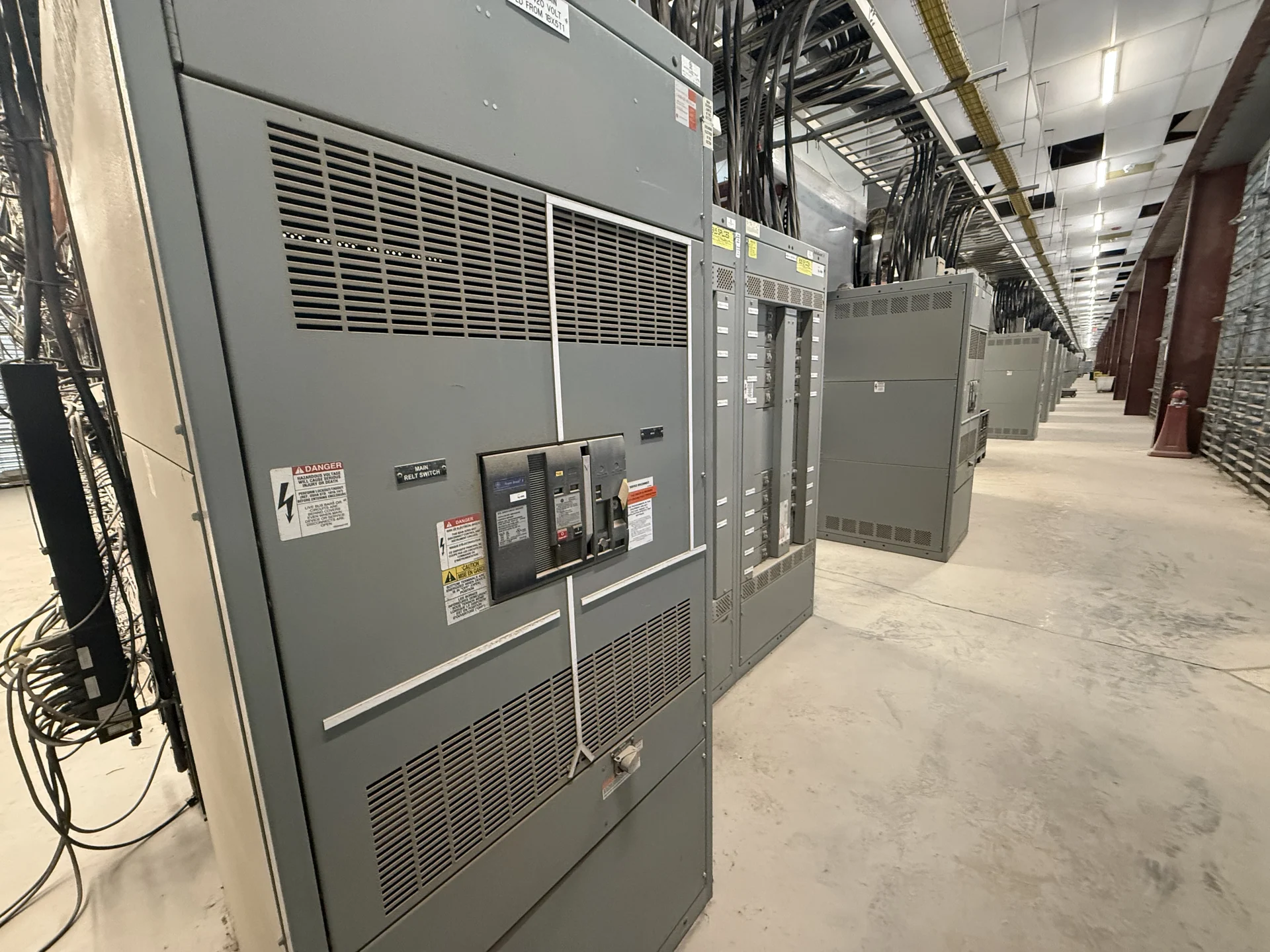
Start with the Process Area and Electrical Duty
Outdoor distribution for oil and gas processes begins with the process equipment, source arrangement, and operating sequence rather than an enclosure label alone. Define whether the lineup serves pumps, compressors, heaters, instrumentation, motor control, or mixed loads, then document voltage, phase, frequency, continuous current, available fault current, grounding method, and feeder requirements. A useful design also identifies normal and alternate sources, required disconnecting points, control interfaces, and any generator or transformer connection. Switchgear Builders manufactures new electrical switchgear in the United States, custom to specification with American components; the project team should provide these engineering inputs before a build is defined.
Match the Enclosure to Outdoor Exposure
An outdoor enclosure must be selected for the actual combination of rain, humidity, condensation, sunlight, dust, salt, washdown, temperature swings, and corrosive vapors at the installation site. The specification should identify the required enclosure type or ingress protection approach, door and gasket expectations, drainage, ventilation, access, and provisions for cable entry. Corrosion resistance is not a single material choice: fasteners, hinges, supports, bus connections, coatings, and interfaces can all affect serviceability. Review the site environment with the electrical engineer and owner, and do not treat a generic outdoor cabinet description as proof that a particular assembly suits a process area.
Address Hazardous-Location Boundaries Carefully
Oil and gas facilities may contain classified areas, but the classification is determined by the site design and applicable requirements, not by the industry name. Identify the boundaries, divisions or zones where applicable, gas groups, temperature limitations, ventilation conditions, and separation from process releases. Equipment placement may be changed by those findings, while wiring methods, glands, conduit interfaces, seals, controls, and maintenance access require coordinated review. A manufacturer can build to an approved project specification, but the owner, engineer, and qualified authorities must establish the site criteria. Do not assume that outdoor switchgear is suitable for a classified location without project-specific evaluation.
Coordinate Protection, Switching, and Controls
Protection and control choices should follow a short-circuit study, load calculations, coordination review, and the intended operating sequence. Specify main and feeder protective devices, interrupting or withstand duties as applicable, trip units or relays, metering, alarms, remote indications, and source interlocks. For motor-driven process loads, consider starting characteristics, coordination with motor protection, and the effect of drives or other power-electronic equipment on the distribution design. Control wiring, terminal identification, segregation, and communication interfaces should be shown on drawings before fabrication. These details help a custom manufacturer build an assembly that fits the electrical system instead of merely matching a nominal ampere rating.
Plan Mechanical Interfaces and Maintenance
Outdoor process equipment must work with the site, not just with the one-line diagram. Confirm foundation dimensions, anchorage, elevation, cable trench or conduit locations, lifting points, working clearances, door swing, removable sections, illumination, drainage, and the route used to place the lineup. Maintenance planning should cover access to breakers, switches, fuses, control terminals, filters or ventilation features if specified, and points that require inspection after weather exposure. Include hazardous-area boundaries and process clearances on the layout. A detailed dimensional review with the installer can prevent conflicts that electrical ratings alone would not reveal.
Define Documentation, Verification, and Delivery
A practical inquiry for outdoor distribution should request a defined document package: approved one-line and schematic drawings, equipment layout, bills of material, device data, terminal schedules, nameplate information, installation interfaces, and project-specific inspection or test records. If UL 891 is relevant, confirm its applicability, construction requirements, and any project-specific listing expectations before design approval; it should not be presumed for every switchgear application. Switchgear Builders supplies new custom equipment nationwide, so the quote request should also state destination, shipping split, packaging, receiving access, lifting limits, and freight responsibilities. Delivery planning remains subject to the specific scope, approvals, and manufacturing review.