Start With the Treatment Process
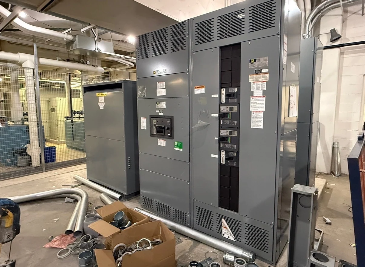
Motor control for water treatment begins with the process rather than a preferred enclosure or device. Identify each pump, mixer, blower, conveyor, chemical-feed unit, and other motor-driven load, then record its normal duty, starting behavior, operating sequence, and consequence of interruption. A clear process schedule helps the manufacturer organize a new motor control center around actual feeders and controls. It also gives the engineer and installer a basis for separating continuously operating equipment from duty-standby pairs, intermittent loads, and equipment that must respond to level, pressure, flow, or treatment-stage signals. Switchgear applications in this environment should be treated as coordinated electrical assemblies, not isolated starter selections.
Choose Starters or Variable Frequency Drives
Across-the-line starters can be appropriate for motors whose starting current, mechanical stress, and speed requirements fit the system, while variable frequency drives can support controlled acceleration, adjustable speed, and process-oriented pumping where the design calls for those functions. The choice affects heat dissipation, bypass provisions, harmonic considerations, control signals, maintenance access, and the physical arrangement of the lineup. A useful specification states motor voltage, horsepower, full-load current, starting method, commanded speed range, bypass expectations, and required local or remote controls. Those inputs allow a custom builder to distinguish a simple starter bucket from a drive section that needs additional electrical and environmental review.
Coordinate Protection and Control
Water-treatment motor control must connect motor protection with the upstream distribution design and the process control scheme. Provide the available fault current, feeder arrangement, grounding approach, motor data, protective-device preferences, and any coordination study assumptions for review. For each motor, define overload behavior, short-circuit protection, disconnecting means, interlocks, permissives, alarm contacts, and trip-reset logic. Pumps may need alternation, lead-lag sequencing, dry-run protection, or automatic restart rules, but those functions should come from the project control narrative rather than assumptions. The resulting drawings should show power paths and control terminals clearly enough for panel integration, field wiring, commissioning checks, and future troubleshooting.
Plan the Enclosure for the Site
A treatment plant exposes electrical equipment to practical site constraints that belong in the equipment inquiry. Confirm indoor or outdoor placement, moisture and corrosion exposure, washdown conditions, ambient temperature, elevation, hazardous-area requirements if applicable, cable-entry direction, ventilation, access space, and the route from unloading point to final foundation. The lineup may need room for incoming power, motor sections, controls, communications, spare ways, and service access, but available space should be balanced against heat, wiring complexity, and maintenance needs. Supply the floor plan, conduit schedule, mounting details, and lifting or shipping restrictions so the manufacturer can develop dimensions and interfaces for project review rather than guessing at a generic plant layout.
Define Communications and Operator Interfaces
Modern water and wastewater facilities often connect motor control to a supervisory system, but the communications scope must be stated precisely. Identify the controller or supervisory platform, preferred protocol, hardwired status points, analog references, network architecture, local selector positions, HOA functions, alarm priorities, and loss-of-communication behavior. A drive may expose more operating data than a starter, yet useful integration depends on the points the plant actually monitors and controls. Include terminal numbering, network-device responsibilities, shield and grounding practices, and whether field instruments are furnished separately. These details help align the custom electrical assembly with the instrumentation and controls design and clarify which network features are included.
Build a Complete Manufacturer Package
A strong request for new motor control equipment includes the one-line diagram, motor schedule, control narrative, sequence of operations, site and enclosure information, equipment dimensions, cable-entry requirements, and requested drawings. Switchgear Builders manufactures custom electrical switchgear in the United States, using American components and supplying new equipment with nationwide shipping; project-specific scope, component selection, and shipping details still require confirmation. Ask for arrangement drawings, elementary or wiring diagrams, device schedules, nameplate information, and an agreed inspection or test record format. The electrical engineer, controls integrator, contractor, and owner should review interfaces before release so the delivered assembly can be installed and connected according to the approved project documents.