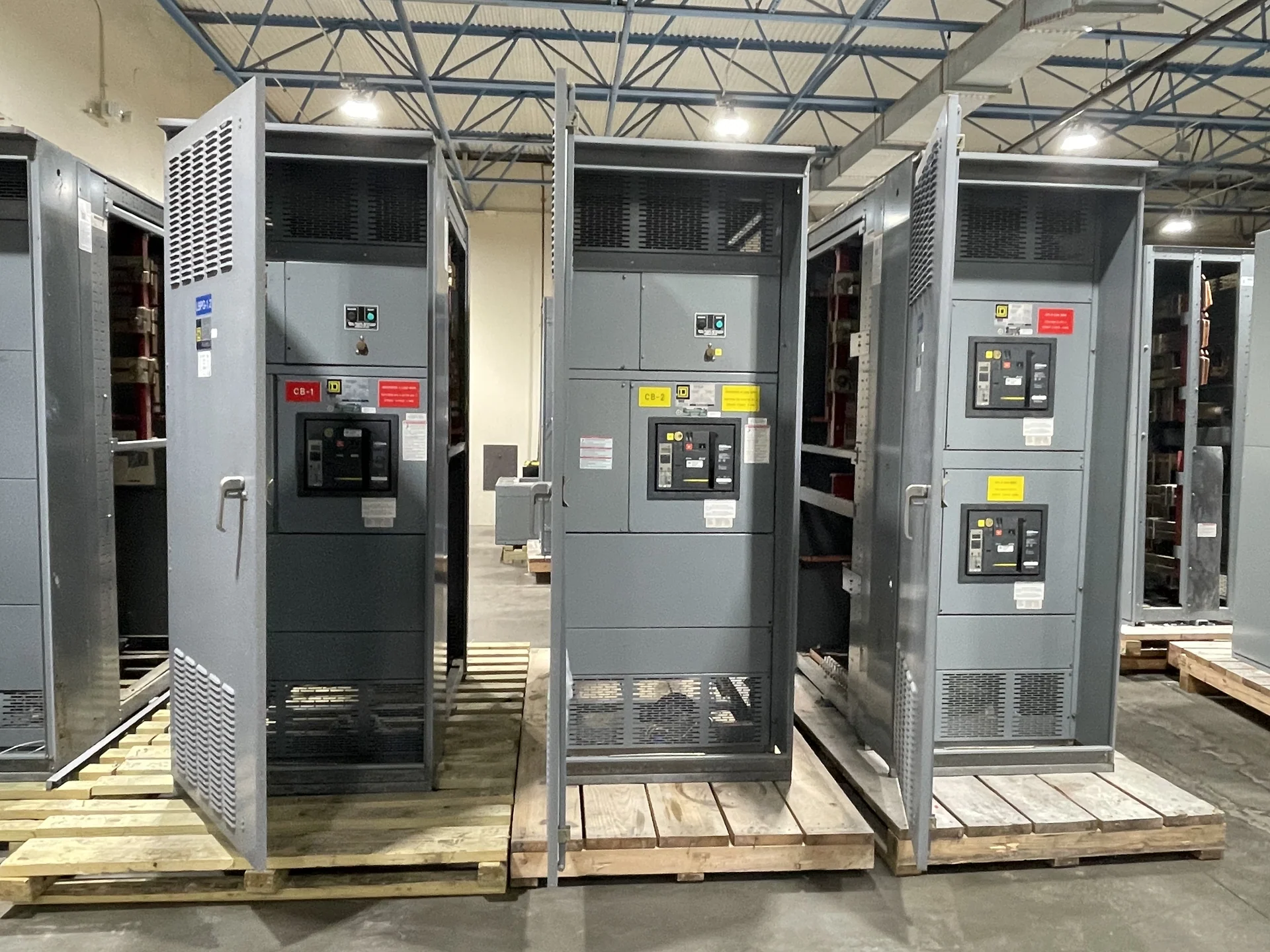
A Motor Control Center at a Glance
A motor control center, commonly called an MCC, is a coordinated electrical assembly that places motor starters, branch-circuit protection, disconnecting means, controls, and related distribution components in one lineup. Instead of scattering motor feeders across separate enclosures, an MCC organizes them into sections that can be specified, wired, identified, and serviced as a system. The exact arrangement depends on the facility’s voltage, available fault current, motor loads, environmental conditions, and operating sequence. An MCC is not automatically interchangeable with switchgear or a general-purpose switchboard; its construction and devices should match the motor-control duties defined by the project engineer.
What an MCC Section Contains
Individual MCC sections may contain across-the-line starters, variable frequency drives, soft starters, feeder breakers, fused disconnects, control transformers, relays, metering, or communication hardware, depending on the design. A starter typically combines a switching device with overload protection and a control circuit, while a feeder unit supplies protection and isolation for a downstream motor controller. The lineup can also include incoming mains, bus ties, spare spaces, and horizontal or vertical bus arrangements. Device selection should follow motor horsepower, full-load current, starting method, fault duty, coordination requirements, and the controls narrative rather than a generic unit schedule.
Selecting the Right Motor-Control Arrangement
MCC planning begins with a complete motor list and a clear description of how each load operates. Useful inputs include motor voltage and phase, rated current, service factor, starting frequency, acceleration expectations, reversing or inching needs, emergency-stop logic, environmental exposure, and whether a drive is required. The engineer should also identify the incoming source, short-circuit study information, grounding method, spare capacity, enclosure requirements, and network protocol if controls will communicate with a plant system. These details help distinguish a compact starter lineup from an arrangement requiring drives, metering, bypass equipment, or specialized control compartments.
Controls, Protection, and Coordination
An MCC connects power distribution decisions with automation and motor protection. Control wiring may carry start-stop commands, permissives, interlocks, status contacts, fault indications, speed references, and signals to a programmable controller. Protective settings must be coordinated with upstream and downstream devices so a fault or overload is addressed at the intended point, subject to the project study and applicable requirements. Drive sections add considerations such as heat dissipation, harmonics, motor-cable length, bypass logic, and maintenance access. A documented control schematic and I/O list reduce ambiguity between the MCC builder, controls integrator, electrician, and commissioning team.
Physical Layout and Installation Interfaces
The physical lineup must fit the electrical room, process area, or outdoor location without compromising access or cable routing. Confirm overall dimensions, shipping splits, lifting points, anchorage, front and rear working space, incoming cable direction, wireway capacity, and the location of field terminals before fabrication. Heat from drives and other electronic devices may influence ventilation and spacing, while dust, moisture, corrosive atmospheres, and washdown conditions affect enclosure selection. The installation package should identify feeder entry points, grounding connections, unit labeling, and responsibilities for field control wiring so the finished assembly matches the site plan.
Buying a New Custom MCC from a Manufacturer
When purchasing a new motor control center, provide the manufacturer with the one-line diagram, motor schedule, control narrative, floor plan, available fault-current information, environmental requirements, and desired documentation. Switchgear Builders manufactures new custom electrical equipment in the United States, using American components and offering nationwide shipping; the final configuration remains dependent on the project’s engineering review and approved drawings. A useful quote should identify mains and feeders, starter or drive types, enclosure conditions, metering, communications, testing, shipping splits, and required submittals. If UL 891 is relevant to the assembly, confirm its applicability and any project-specific listing requirements before the design is finalized.