Plan the Orlando Distribution Interface
An Orlando electrical distribution project should begin with the facility's one-line diagram, service arrangement, connected load study, and operating priorities rather than with a standard lineup assumption. A new switchgear package may need to coordinate utility service, generators, transformers, automatic transfer switches, feeders, and emergency or legally required loads. Identify the nominal voltage, phase and wire configuration, frequency, continuous current, available fault current, grounding method, and environmental conditions. Those inputs let a manufacturer develop equipment around the actual site instead of forcing the design into an unsuitable enclosure or device arrangement.
Separate Critical Loads from General Loads
Critical facility loads in the Orlando area can include life-safety systems, communications, process equipment, refrigeration, water systems, or selected building services, but the project team must define which loads truly require an alternate source. Grouping loads by source, priority, starting behavior, and allowable interruption helps determine whether separate transfer switches, dedicated feeders, selective load shedding, or staged restoration are appropriate. The switchgear design should show how normal and alternate sources reach each load group, where isolation occurs, and which operating conditions require manual intervention or automatic sequencing.
Specify Automatic Transfer Switch Operation
Automatic transfer switches are not interchangeable simply because their ampere ratings appear similar. The specification should identify source voltage, system grounding, transition method, number of poles, bypass or isolation needs, controls, sensing points, time delays, and the desired response to source loss, generator availability, retransfer, and source restoration. A useful sequence of operation explains what happens during undervoltage, phase problems, generator warm-up, load shedding, and a failed alternate source. The manufacturer can then coordinate switchgear compartments, feeder terminations, control wiring, interlocks, and maintenance access with that sequence.
Account for Florida Site Conditions
A Florida installation requires the design team to discuss exposure, moisture, heat, corrosion potential, wind-related site conditions, drainage, and the difference between an indoor electrical room and an outdoor equipment location. These conditions influence enclosure selection, ventilation, cable entry, door and gasket details, finish expectations, anchorage interfaces, and the location of control equipment. They do not establish a particular enclosure rating automatically; the engineer and authority having jurisdiction should identify the applicable requirements, while the equipment design records the selected conditions and assumptions for review.
Coordinate Protection and Maintenance Access
Protection settings and transfer logic should be reviewed together because an automatic source change can alter fault contribution, feeder loading, and coordination behavior. Provide the available fault-current study, transformer data, generator characteristics, protective-device schedules, and intended time-current coordination approach when requesting a quote. Physical planning matters as well: confirm lineup dimensions, working space, cable bending room, lifting and movement paths, breaker or switch service access, control-panel visibility, and a safe method for isolating equipment during planned maintenance.
Build and Ship New Equipment to the Project
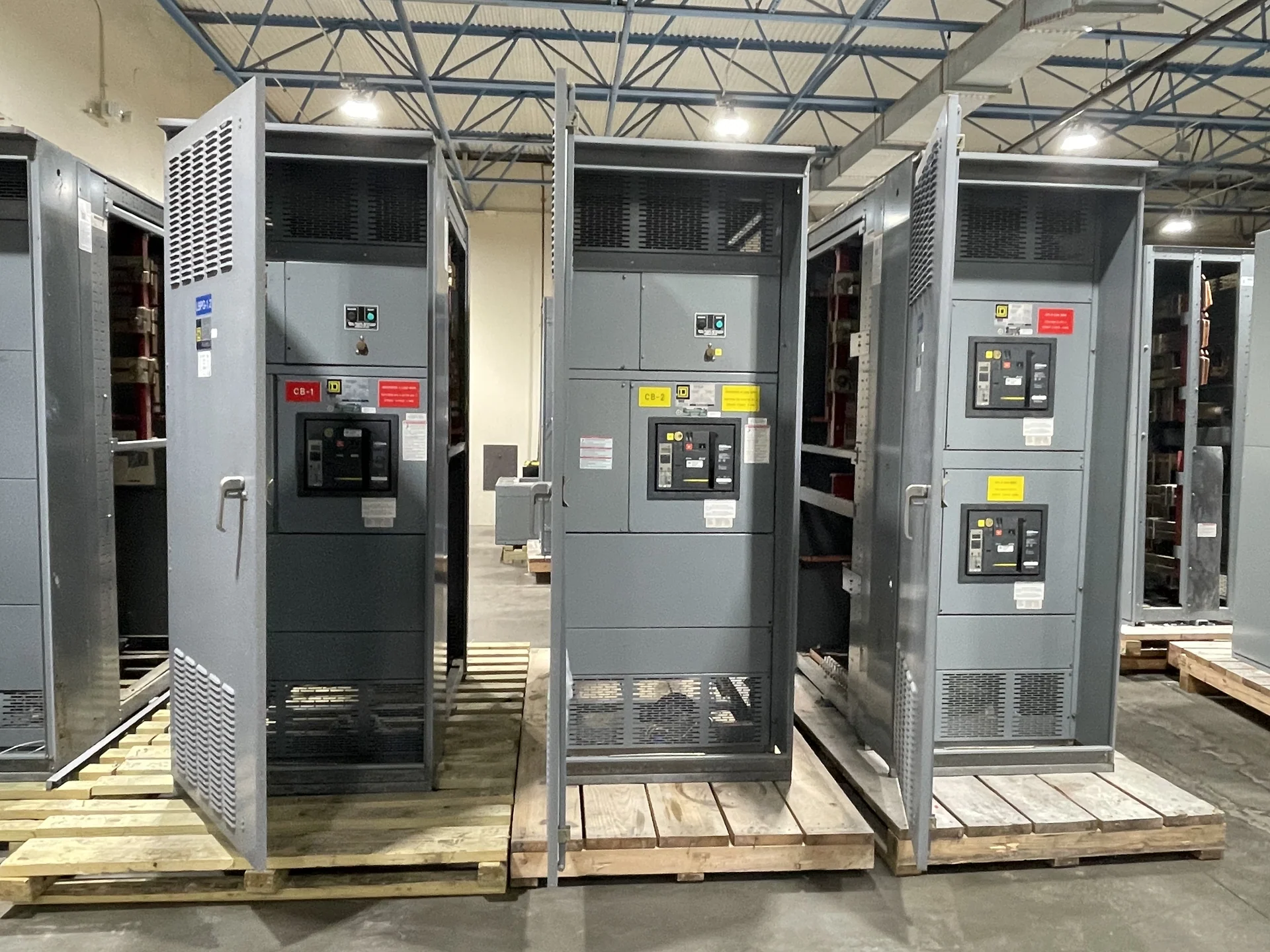
Switchgear Builders manufactures new electrical switchgear in the United States, builds custom equipment to the project's electrical and physical requirements, uses American components, and ships nationwide. A quote request for an Orlando project should include drawings, schedules, site address, receiving constraints, shipping splits, unloading responsibility, and the desired documentation package. Coordinate the delivery plan with the electrical contractor so the site can receive, inspect, stage, position, anchor, and connect each shipping section according to approved drawings and qualified installation procedures. If a switchboard or switchgear assembly may fall under UL 891, confirm that standard's applicability and any project-specific listing or capability during engineering review; it should never be assumed from the product name alone.