Start with the Commercial Building Distribution Plan
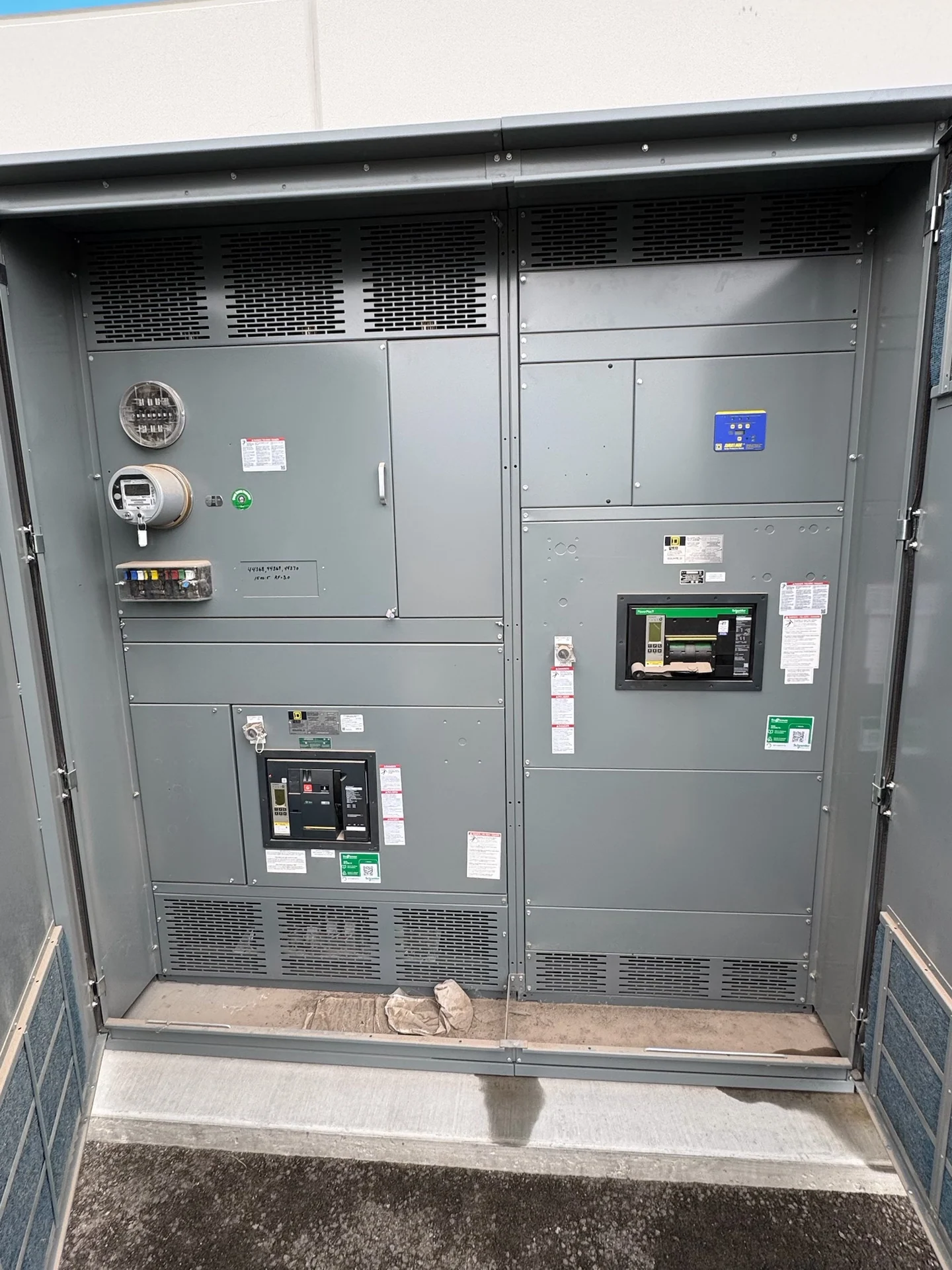
Low-voltage switchgear for commercial buildings in Orlando, Florida should begin with a documented distribution plan rather than a preferred enclosure or breaker arrangement. Gather the service concept, utility information, transformer relationship, normal and standby sources, one-line diagram, calculated loads, and intended feeder destinations. A manufacturer can then evaluate a new custom assembly around the project's actual interfaces. The same discipline helps an owner, engineer, and electrical contractor keep equipment scope aligned while a building is designed, renovated, or expanded. Record assumptions separately from confirmed design data so later revisions can be traced instead of silently changing the equipment basis.
Define Voltage, Current, and Fault Duty
The equipment inquiry should identify nominal system voltage, phase and wire configuration, frequency, grounding method, continuous current requirements, and available fault current at the proposed lineup. Main and feeder devices need ratings appropriate to their duties, while bus capacity and bracing must correspond to the specified assembly requirements. Do not infer these values from a building type or city. Have the design team confirm calculations, utility data, transformer details, and protective-device coordination before requesting a manufacturer quote for low-voltage switchgear. Include the source of each critical value, because utility revisions or transformer changes can alter the final equipment basis.
Coordinate Main and Feeder Protection
Commercial distribution often combines a service main, multiple tenant or mechanical feeders, emergency-related loads, and equipment that may operate on different schedules. Identify which circuits require metering, shunt functions, undervoltage features, ground-fault protection, or other project-defined controls, then document the desired operating sequence. Time-current coordination and arc-flash study inputs should be reviewed by qualified electrical professionals. The resulting settings and device selections belong in the project design, not in assumptions made from a generic switchgear description. Clarify who supplies relaying information, who approves settings, and how control terminals interface with building systems before drawings are finalized.
Fit the Lineup to the Electrical Room
Room planning is as important as electrical ratings. Confirm the available wall length, lineup depth, working space, maintenance access, doorway dimensions, turning path, floor conditions, cable-entry direction, and locations of nearby piping or ventilation. Account for sections that may be shipped separately and reassembled at the project site, if that approach suits the design. For an Orlando commercial project, review site conditions, building logistics, component availability, and installation responsibilities for the proposed order. Coordinate structural loading, housekeeping pads, conduit routes, and access-control restrictions with the building team before approving the physical layout. For a multitenant property, map each tenant or common-area feeder to its upstream disconnect and downstream panel so naming stays consistent across the one-line, schedules, labels, and commissioning records. Note whether shell space, retail turnover, kitchen equipment, or central plant expansion is included in the current design; these distinctions prevent an allowance from being mistaken for a present load. In Orlando, confirm whether the lineup travels through a loading dock, garage, or active tenant route, and coordinate delivery protection, staging, and elevator restrictions with the site manager. Those details can change section dimensions, split points, and the sequence for placing equipment.
Plan Future Capacity Without Oversizing Blindly
Future loads should be described with enough detail to support a defensible decision: expected tenant changes, electric heating or cooling additions, charging infrastructure, data or communications spaces, elevators, pumps, and standby loads may affect feeder allocation and spare provisions. Extra physical space, bus capacity, or device positions can influence cost and room dimensions, while excessive capacity may complicate the design without serving a defined need. Ask the engineer to separate confirmed loads from planning allowances before finalizing the custom equipment scope. That distinction also makes later review easier when tenants, operating hours, or mechanical systems change during design development.
Request a Complete New Equipment Package
When the design is ready, send the manufacturer the one-line diagram, schedules, ratings, enclosure environment, dimensions, control narrative, metering requirements, drawing standards, inspection expectations, and destination details. Switchgear Builders manufactures, builds, and supplies new electrical switchgear in the United States, custom to specification with American components and nationwide shipping. Any applicable standard, including possible UL 891 consideration, must be identified and confirmed for the specific project. A clear package supports review of drawings, factory checks, shipping sections, receiving access, field coordination, and project-specific requirements. Confirm responsibilities for unloading, storage, placement, and field connections before shipment coordination.