Start with the Critical-Load Operating Requirement
Automatic transfer switches for critical loads in Chicago, Illinois, should be selected from the operating consequence backward rather than from a catalog label. Identify which loads must remain energized, which may pause briefly, and which should be shed during a constrained source condition. Hospitals, data rooms, life-safety systems, process controls, and public infrastructure can have different continuity objectives. A load schedule should show voltage, phase, frequency, connected and demand current, motor starting effects, and whether each load belongs on one source, a redundant path, or a priority sequence. Also identify loads that cannot tolerate a transfer interruption, loads with large inrush, and systems that need a defined restart order. That information gives the manufacturer a defensible basis for a new custom equipment package and helps the engineer explain the intended operating result to installers and operators.
Define Source Capacity and Compatibility
Source capacity is more than the nominal rating of a transfer switch. The project team should document normal and alternate source characteristics, available fault current, generator transient behavior, conductor arrangements, grounding method, upstream overcurrent protection, and the largest loads that can start during transfer. Confirm whether the alternate source can carry the full critical-load block or whether staged pickup is required. For a Chicago installation, the design should also account for the actual building service arrangement, electrical-room dimensions, cable routing, ambient conditions, and utility or authority requirements; location alone does not determine an equipment configuration. Include transformer impedance, generator subtransient information when available, and the expected voltage and frequency acceptance windows. These inputs allow source sensing and protective-device choices to be reviewed together rather than treated as isolated selections.
Set the Transfer Sequence Before Fabrication
A useful transfer sequence states what the switch monitors, when it declares a source acceptable, how long it waits before transferring, and what happens if the preferred source returns or the alternate source fails. Decide whether the project needs open transition, closed transition, delayed transition, bypass or isolation provisions, or a separate load-shedding strategy; each choice affects controls, interlocks, wiring, and operating procedures. Specify retransfer timing, generator start contacts, cooldown behavior, manual controls, alarm points, and remote status signals in plain language. The manufacturer can then coordinate a custom build to the approved sequence instead of inferring control intent from a device name alone. Include abnormal cases such as a failed start, undervoltage during transfer, an unavailable alternate source, and a manual transfer request. A written matrix of source states and expected actions is particularly useful during review and functional testing.
Coordinate Protection and Distribution Interfaces
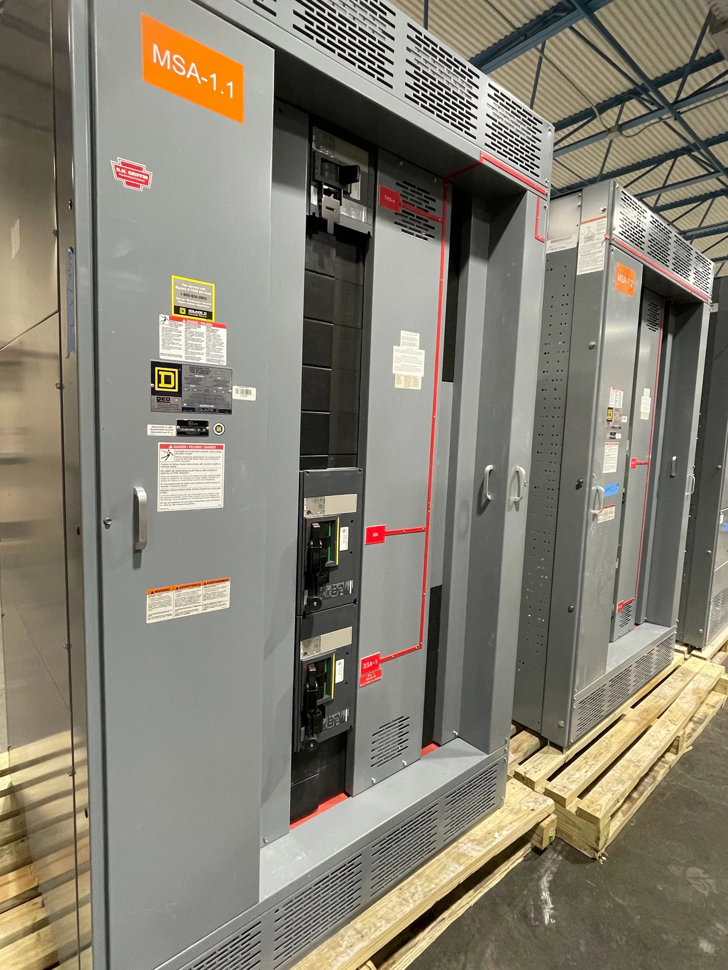
Protection must be reviewed across both sources and the downstream critical-load distribution. Gather breaker trip settings, short-circuit calculations, selective-coordination objectives, ground-fault requirements, transformer data, and any protective-relay logic that interacts with transfer operation. A transfer switch is not a substitute for a coordination study, and an automatic command does not remove the need to verify interrupting duties and conductor protection. Drawings should identify source disconnects, bypass paths if applicable, neutral treatment, sensing conductors, control power, and communication interfaces. A project-specific review can determine which components and documentation belong in the new switchgear assembly. Ask the engineer to resolve whether the neutral is switched, how separately derived sources are grounded, and how maintenance controls interact with automatic operation. Those decisions should appear consistently in the one-line, wiring diagrams, settings documentation, and field checkout plan.
Plan Maintenance Access, Delivery, and Review
Maintenance planning should be visible in the physical layout before a quote is finalized. Provide the equipment footprint, front and rear access expectations, door swing, working clearances, lifting or movement path, cable-entry direction, ventilation needs, and the space required to inspect or service switching and control components. Ask for drawings showing terminals, labels, interlocks, and test points, then align those documents with the installer’s field responsibilities. Consider how an operator will isolate a source, verify an indication, exercise a manual control, and return the equipment to automatic operation without obstructing adjacent gear. Switchgear Builders manufactures new electrical switchgear in the United States, custom to specification with American components and nationwide shipping; destination details, packaging, freight access, and project timing still need confirmation for each Chicago shipment.