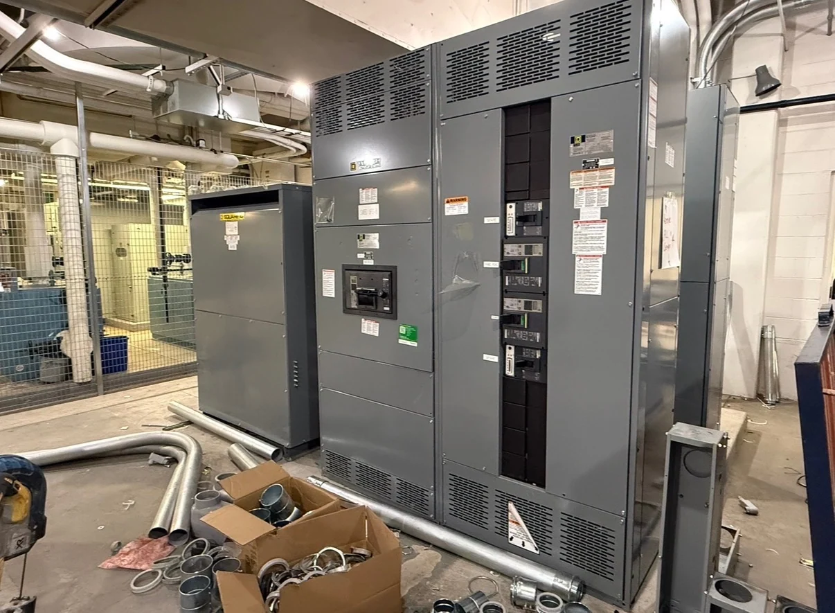
Start with the Newark project electrical picture
A Newark, New Jersey facility may combine utility service, process areas, conveyors, pumps, and support loads that do not share the same operating profile. For a Newark project, document whether the lineup serves a dense urban facility, a port or logistics operation, or an industrial campus, because access and outage planning can differ substantially. Record transformer locations, utility service boundaries, and the route for incoming and outgoing feeders. If equipment must pass through a constrained loading area, capture door widths, turning clearances, floor loading limits, and rigging restrictions early. For phased work, identify which existing feeders remain energized, where temporary power is needed, and how shutdowns will be sequenced. Include winter exposure, road access, and receiving-hour constraints when defining the shipment and installation plan. These details help align the equipment footprint with Newark site conditions. A useful switchgear or motor-control specification begins with the single-line diagram, nominal voltage, phase and frequency, available fault current, grounding method, calculated load, and expansion allowance. Identify which loads must operate together, which can be sequenced, and which require source transfer or selective isolation. Switchgear Builders manufactures new electrical switchgear in the United States, custom to specification with American components and nationwide shipping.
Match motor starters and drives to the loads
Industrial pumps, conveyors, and process loads impose different starting and running demands. A pump may need attention to starting torque, cycling, and controlled acceleration; a conveyor may require coordinated starts, reversing logic, or jam response; a process load may need a variable frequency drive, bypass arrangement, or defined restart behavior. The equipment schedule should identify motor horsepower, full-load current, starting method, duty, overload approach, and any harmonic or heat considerations. Those inputs let the manufacturer evaluate a coherent lineup rather than treating every feeder as interchangeable.
Define protection and coordination inputs
Motor protection should be coordinated with feeder protection, upstream devices, conductor ampacity, and the facility operating sequence. Provide the engineer’s short-circuit study or available fault-current information, protective-device preferences, time-current coordination goals, ground-fault requirements where applicable, and settings responsibility. Circuit breakers, fuses, overload relays, and drive protection each address different conditions, so the selected arrangement should follow the equipment duty and study results. A Newark electrical distribution package should also state whether maintenance isolation, local control, remote control, or lockable disconnect functions are required.
Plan the control interface before fabrication
Control details often determine whether a motor-control center integrates cleanly with the rest of a process. Document hardwired interlocks, permissives, emergency-stop circuits, run and fault indication, remote start commands, analog signals, network communications, and the intended fail state for lost control power. Show terminal points and cable entry expectations on the drawings, and distinguish field wiring from factory wiring. If drives or intelligent devices are included, identify the desired data, protocol, addressing responsibility, and commissioning checks without assuming a particular platform.
Coordinate enclosure, installation, and shipping details
Physical planning matters as much as the electrical schedule. Confirm indoor or outdoor exposure, ambient conditions, enclosure requirements, available wall or floor space, working clearances, cable-termination direction, doors and access panels, lifting points, shipping splits, and the route from the receiving area to the final installation. The project team should assign responsibilities for anchorage, field terminations, control cables, rigging, and inspection at receipt. Switchgear Builders can build new equipment custom to the approved requirements and coordinate nationwide shipment terms around the specified destination and handling plan.
Prepare a complete manufacturer quote request
For a productive quote request, send the latest one-line diagram, motor and feeder schedules, fault-current data, control schematics, physical drawings, environmental information, applicable owner or utility requirements, and the desired documentation package. State whether the scope is a new lineup, an expansion interface, or replacement within an existing distribution arrangement, then identify required review milestones and witness expectations. Include motor data sheets, sequence-of-operation narratives, network diagrams, cable schedules, and room access constraints when available. Ask the manufacturer to identify assumptions, exclusions, component choices, shipping scope, and project-specific standards review so the proposal can be evaluated on equivalent technical content. Clarify who will approve drawings, set protective devices, terminate field wiring, perform functional checks, and authorize energization. That division of responsibility prevents a technically complete enclosure from being mismatched with the installation or controls commissioning plan.