Start With the Water-Process Load Profile
Ohio water and wastewater projects often combine large pumps, aeration equipment, chemical systems, solids handling, HVAC, and building services on one coordinated electrical distribution plan. A manufacturer-built motor control center should begin with the process load schedule rather than a preferred enclosure or starter arrangement. Identify each motor's voltage, horsepower, full-load current, starting method, duty cycle, reversing requirements, and control source. Separate continuously operating loads from intermittent or standby loads, then document which pumps must operate together. This information gives the design team a practical basis for feeder sizing, short-circuit review, heat planning, and a custom equipment quote.
Coordinate Motor Starting and Drive Selection
Motor starting decisions affect both the motor control center and the upstream distribution system. Across-the-line starting may simplify a small, straightforward load, while reduced-voltage starting or a variable frequency drive can change inrush, acceleration, control behavior, harmonics, heat dissipation, and maintenance access. A water-treatment specification should state whether a pump needs constant speed, adjustable flow, soft acceleration, bypass operation, or a defined response to a process signal. Engineers should also identify minimum and maximum operating speeds, overload requirements, bypass preferences, and line-side or load-side disconnect expectations before the manufacturer lays out the lineup.
Translate Controls Into a Buildable Layout
Controls for Ohio treatment facilities may involve local stations, remote commands, level instruments, flow transmitters, programmable controllers, interlocks, alarms, and supervisory systems. A useful control narrative should describe permissives, start and stop priorities, fault responses, reset behavior, lead-lag rotation, and automatic alternation for redundant pumps. Provide the desired terminal arrangement, communication interfaces, control voltage, and segregation expectations so the custom builder can reflect those interfaces in drawings. Clear point lists reduce ambiguity between the motor control center, field instruments, process controls, and the installing electrical contractor.
Account for Ohio Site Conditions
Site conditions can change the appropriate enclosure, materials, ventilation approach, and installation details. Confirm whether the lineup will be indoors, in a conditioned electrical room, or in an area exposed to moisture, washdown, condensation, dust, corrosive treatment chemicals, or seasonal temperature swings. Record elevation, available floor space, cable entry direction, housekeeping pad dimensions, access paths, working clearances, and anchoring expectations. The project team should establish environmental and enclosure requirements from the actual room and process area; a location in Ohio alone does not determine the correct equipment construction.
Review Protection and Distribution Interfaces
The motor control center must fit the complete distribution system, including the upstream transformer or switchgear, feeder conductors, grounding method, and downstream motors. Supply the one-line diagram, available fault-current information, system voltage and frequency, phase and wire arrangement, protective-device preferences, and coordination-study assumptions. Check that feeder and branch protective devices address motor starting characteristics and conductor requirements without treating a catalog term as an automatic design conclusion. Where the facility has emergency generation, transfer equipment, or essential process loads, define the source sequence and the loads that may operate during each operating mode.
Plan Drawings, Inspection, and Installation
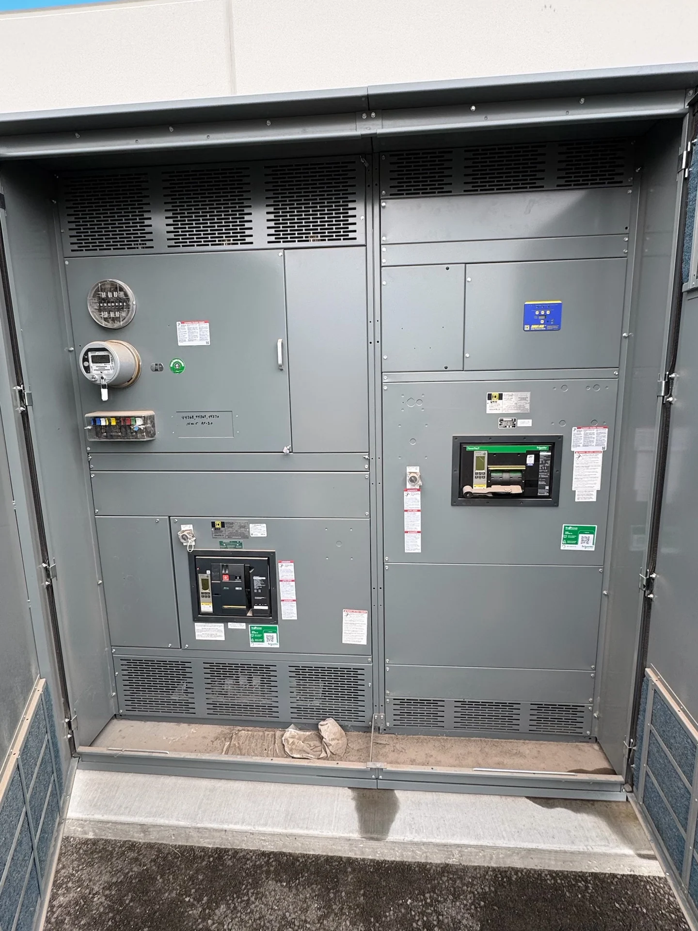
A disciplined project package should identify drawing milestones, review responsibilities, nameplate data, wiring diagrams, terminal schedules, device lists, and the records expected at shipment. Before fabrication, the engineer and installer can confirm lineup dimensions, shipping splits, lifting provisions, cable bend space, conduit routes, and the intended field connections. Inspection and electrical checks should follow an agreed project test plan with acceptance criteria defined in advance. The equipment manufacturer can build and supply new custom switchgear with American components and coordinate documentation, while the Ohio project team remains responsible for site readiness and installation coordination.
Prepare a Complete Ohio Inquiry
For a useful Ohio switchgear inquiry, send the process description, motor schedule, single-line diagram, control narrative, floor plan, environmental information, required motor control center arrangement, and project documentation standards. Include the destination, receiving constraints, requested shipping configuration, and the parties responsible for unloading and placement. Ask the manufacturer to identify assumptions, exclusions, required engineering inputs, and project-specific service and delivery details rather than relying on generic estimates. Switchgear Builders manufactures new electrical switchgear in the United States, builds custom to specification, supplies American components, and ships nationwide; final scope remains subject to technical review.