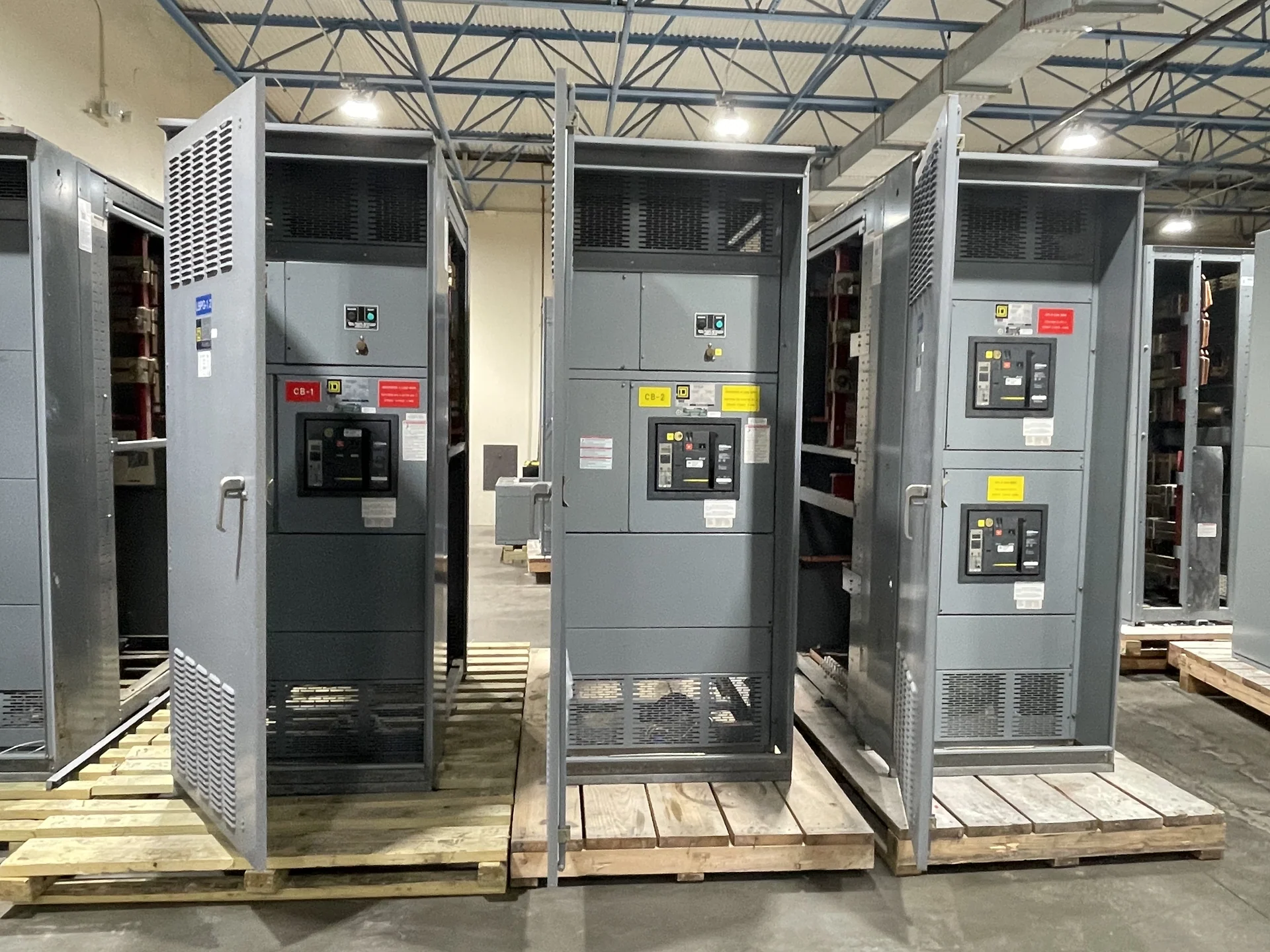
Start with the Critical-Load Plan
A Philadelphia facility considering automatic transfer switches for critical loads should begin with a documented load schedule rather than a switch model. Identify life-safety, process, communications, fire protection, refrigeration, and other loads that require an alternate source, then note their voltage, phase, connected current, starting behavior, and allowable interruption. Separate loads that can transfer together from those needing a staged sequence. This information helps a manufacturer configure new switchgear and transfer equipment around the actual distribution architecture. It also gives the electrical engineer, contractor, and owner a common basis for reviewing source capacity, feeder routing, maintenance access, and the project-specific operating requirements before a quote is prepared.
Define Normal and Emergency Source Capacity
Source capacity is more than the nameplate rating of a generator or utility service. The design team should compare continuous demand, motor-starting current, transformer inrush, nonlinear loads, voltage and frequency behavior, and the effect of other transfer switches operating at the same time. Confirm whether the alternate source is dedicated, shared, or arranged through upstream switchgear, and identify the available fault current at each relevant point. For a Philadelphia project, seasonal conditions, building expansion, and utility coordination may influence the design inputs, but none should be assumed without engineering documentation. Switchgear Builders manufactures custom new electrical switchgear in the United States, using American components and supplying projects nationwide, with final configuration determined by the approved requirements.
Map the Transfer Sequence
An automatic transfer switch should be specified through its operating sequence, not merely its source labels. Describe how the equipment senses loss or unacceptable quality on the normal source, starts or confirms the alternate source, transfers selected loads, and returns them after normal power is stable. Include time delays, retransfer behavior, manual controls, test positions, permissive signals, and any interlocking needed to prevent an unintended source connection. If several critical load groups are involved, show their order and separation on the one-line diagram. A written sequence of operations gives the manufacturer a precise control target and allows the engineer and installer to identify dependencies between transfer equipment, protective devices, generator controls, and building automation.
Coordinate Protection and Grounding
Protection coordination should be reviewed across the normal source, alternate source, transfer equipment, downstream feeders, and critical loads. Provide breaker trip data, transformer information, grounding arrangement, conductor details, and the available fault current used for the design. The engineer can then evaluate selective coordination, short-circuit duty, overcurrent settings, neutral switching, and ground-fault sensing as applicable to the system. Transfer equipment may alter fault-current paths or the timing of protective devices, so the sequence and settings should be checked together rather than in isolation. Project documents should also identify service interface requirements, equipment grounding, bonding, and any authority or utility review that applies to the Philadelphia installation.
Plan Maintenance Access and Testing
Critical-load transfer equipment needs a practical maintenance plan before the lineup is dimensioned. Confirm working clearances, door swing, cable entry, lifting and movement paths, access to controls, isolation points, and room conditions. Decide how periodic exercises, source-failure simulations, alarm checks, and manual operations will be performed without creating an unsafe or unacceptable interruption. The owner should identify who will witness functional checks and what records belong in the turnover package. A manufacturer quote can be more useful when it includes the requested drawings, device schedules, control descriptions, test documentation, and shipping split assumptions, while installation and commissioning responsibilities remain clearly assigned among qualified project participants.
Prepare a New Equipment Inquiry for Philadelphia
For a project-specific inquiry, send the manufacturer the one-line diagram, load schedule, source details, transfer sequence, ratings, enclosure location, dimensions or room constraints, cable-entry preferences, control and communications requirements, protective-device information, documentation list, destination, and requested commercial terms. Explain whether the work is new construction, an expansion, or replacement of a distribution arrangement, and identify outage, rigging, receiving, site-access, and schedule constraints. Switchgear Builders can review a custom new-equipment scope for a Philadelphia, Pennsylvania project, coordinate the proposed build around the supplied engineering information, and arrange nationwide shipping. Any standard, listing, approval, or UL 891 applicability must be confirmed for the specific design and project.