Start with the Rhode Island Process Load
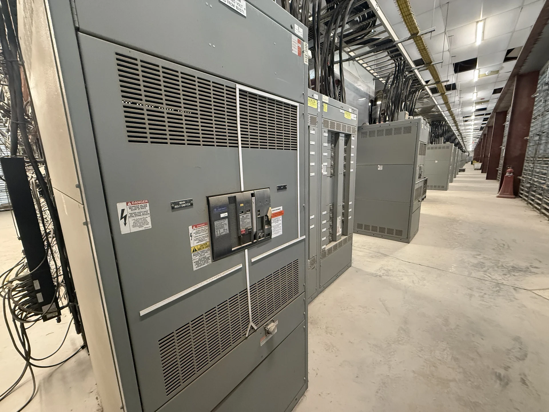
Planning Rhode Island electrical distribution for an industrial facility starts with the process rather than a generic equipment label. Pumps, conveyors, and other process loads can have different starting currents, duty cycles, speed requirements, and consequences when a motor stops. A useful equipment specification identifies each motor, its voltage and phase, horsepower or kW, starting method, operating mode, feeder source, and whether the load is continuous, intermittent, standby, or sequenced. Those inputs let the design team determine whether a motor control center, separate starter sections, drives, or another arrangement fits the application. Switchgear Builders manufactures new custom electrical equipment in the United States, using American components and shipping nationwide; final configuration remains subject to project engineering and the supplied drawings.
Choose Starters and Drives by Operating Duty
Motor protection and starting equipment should reflect how each Rhode Island process motor actually operates. An across-the-line starter may suit a motor whose electrical and mechanical system can tolerate full-voltage starting, while reduced-voltage equipment may be considered when starting effects or mechanical behavior require review. A variable frequency drive can support controlled acceleration, adjustable speed, or process regulation, but it introduces enclosure heat, harmonics, bypass questions, and control coordination that belong in the specification. For conveyors, review loaded starting, reversing or jog functions, and emergency-stop interfaces; for pumps, review minimum-flow operation, pressure control, and dry-run logic. The manufacturer can build to an approved design, but the engineer must establish protection settings, sequence, and applicable requirements for the project.
Coordinate the Control Interface
A motor control center is more useful when its control interface is defined alongside the power components. Identify whether commands originate at a local station, programmable controller, supervisory system, or a combination, and document permissives, interlocks, run feedback, fault indication, remote reset, and loss-of-control-power behavior. Process equipment may require a deliberate start sequence so pumps, conveyors, valves, and upstream or downstream machinery operate in the correct order. The wiring schedule should distinguish control voltage, terminal points, shield or drain requirements, communication connections, and field-installed conductors. Include the intended failure response for overload, drive fault, loss of phase, emergency stop, and process trips. Clear interface information reduces interpretation during fabrication and gives installers a practical basis for point-to-point checks.
Account for Site Conditions and Maintainability
Rhode Island project planning should connect the motor control center design to the actual electrical room, process area, and installation route. Confirm indoor or outdoor placement, ambient conditions, moisture or corrosive exposure, available working space, cable entry direction, floor or housekeeping pad details, lifting access, and the path from receiving to the final location. Layout decisions also affect maintenance: reserve room to operate devices, inspect terminations, withdraw components where applicable, and replace a starter or drive without obstructing adjacent equipment. Ask the installing team to review section dimensions, shipping splits, conduit approach, anchorage, and field connections before drawings are approved. These practical constraints can change the enclosure arrangement even when the electrical one-line remains unchanged.
Build a Complete Manufacturer Quote Package
A request for new Rhode Island switchgear or a motor control center should include the one-line diagram, motor schedule, control schematics, floor plan, feeder data, fault-current information, environmental conditions, and the desired documentation. State which starters, drives, overload functions, metering, communications, spare spaces, and control devices are required, while separating confirmed requirements from design options. Identify who provides field instruments, network equipment, programming, conduit, and installation so the equipment scope is understandable. Switchgear Builders can review a custom specification for a new manufacturer-built package and coordinate the design around supplied interfaces. Ask for project-specific component details, drawings, test scope, shipping terms, and delivery estimates; do not assume service coverage, current availability, or schedule until those items are confirmed for the project.
Plan Shipping, Installation, and Verification
Nationwide shipping does not remove the need for a receiving and installation plan. Before release, establish the destination, site contact, unloading equipment, storage conditions, shipment sections, lifting points, and responsibility for moving the assembly into position. At receipt, the qualified project team should compare packages with shipping documents, inspect for visible transit damage, preserve documentation, and report discrepancies through the agreed process. Installation then requires field verification of grounding, power and control terminations, device labels, rotation, network connections, and interlocks before energization. Define the inspection and test records needed by the engineer, owner, and installer, including any factory checks or witness points agreed in the purchase documents. Service and delivery details are project-specific and should be confirmed directly with the manufacturer.