Start With the Casper Project Definition
A Casper, Wyoming electrical distribution project should begin with the facility plan rather than a product label. Identify whether the work adds capacity for an expansion, supplies a new building area, replaces a lineup, or creates new feeders from an established source. Gather the one-line diagram, service and feeder information, load calculations, system voltage, phase and frequency, grounding method, available fault current, and operating sequence. Also document the project location, indoor or outdoor environment, elevation considerations when relevant, access route, and installation responsibilities. These inputs let an American switchgear manufacturer develop a new custom-to-specification package instead of treating a site-specific distribution problem as a generic purchase.
Plan New Feeders Around the Existing System
New electrical feeders must connect cleanly to the system already serving the Casper facility. Review source capacity, bus arrangement, feeder destinations, conductor routing, termination space, protective-device coordination, grounding and bonding, metering interfaces, and control wiring. Existing equipment dimensions and connection points should be measured and compared with current drawings, because field conditions can differ from records. A manufacturer can use those details to coordinate a new lineup or section with the engineer and installer. The design should clearly identify what is furnished, what is field-installed, and which shutdowns or tie-ins require an approved sequence before construction begins.
Account for Wyoming Site Conditions
Casper site conditions should influence enclosure and layout decisions without being guessed from the city name alone. Confirm whether equipment will be indoors, outdoors, in a heated or unheated space, or exposed to dust, moisture, wind, temperature swings, or corrosive agents. Record the room dimensions, working clearances, ceiling height, floor loading, door openings, turning radius, and path for delivery and rigging. For outdoor equipment, define the foundation interface, cable entries, drainage expectations, access control, and environmental enclosure requirements. These facts support a practical build and help the project team resolve site constraints before fabrication and nationwide shipment.
Coordinate Expansion and Outage Windows
Facility expansion often requires electrical work to occur around occupied operations, production, tenants, or critical loads. Separate the design review from the outage plan: first establish ratings, dimensions, interfaces, protection, and controls; then map isolation points, temporary arrangements if any, demolition boundaries, testing responsibilities, and energization steps with qualified project personnel. Provide the manufacturer with the required delivery destination, shipping split preferences, lifting restrictions, receiving contact, and site access limits. A realistic schedule can only be discussed after scope, approvals, component choices, fabrication requirements, and transportation details are reviewed for the particular order.
Build a Clear Custom Switchgear Package
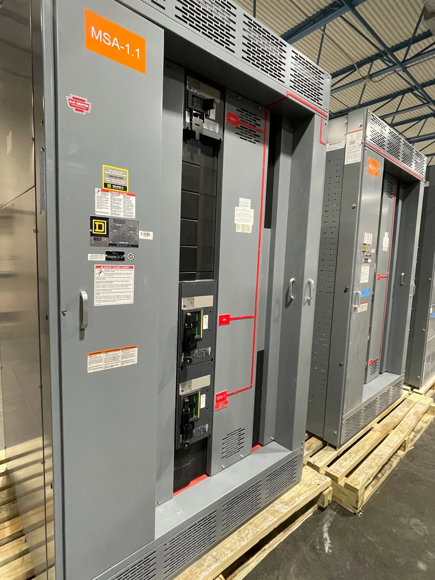
A useful quote request for Casper switchgear should state the equipment type, nominal voltage, continuous current, short-circuit duty, main and feeder arrangement, breaker or switch preferences, bus material, enclosure conditions, dimensions, cable entry direction, metering, protective relaying, control voltage, communication needs, and required drawings. Include the project single-line, schedule, site photos or measurements, specification sections, and any engineer comments. Switchgear Builders manufactures new electrical switchgear in the United States, builds custom equipment to project requirements, uses American components, and supplies projects with nationwide shipping. Component origin, manufacturing details, and shipping terms should still be confirmed for the specific package.
Review Drawings, Testing, and Delivery Details
Before release, review the equipment layout against the Casper room or yard, then check the one-line, wiring diagrams, device schedules, nameplate information, terminal points, labels, and installation interfaces. Agree on inspection points, electrical checks, functional checks, and records that belong in the project test plan; do not assume a test scope or certification without written project confirmation. If UL 891 is referenced, confirm whether it applies to the proposed assembly and what project-specific listing or verification is required. At shipment, coordinate packaging, shipping sections, weights, lifting points, freight terms, receiving inspection, storage, and the qualified rigging plan.