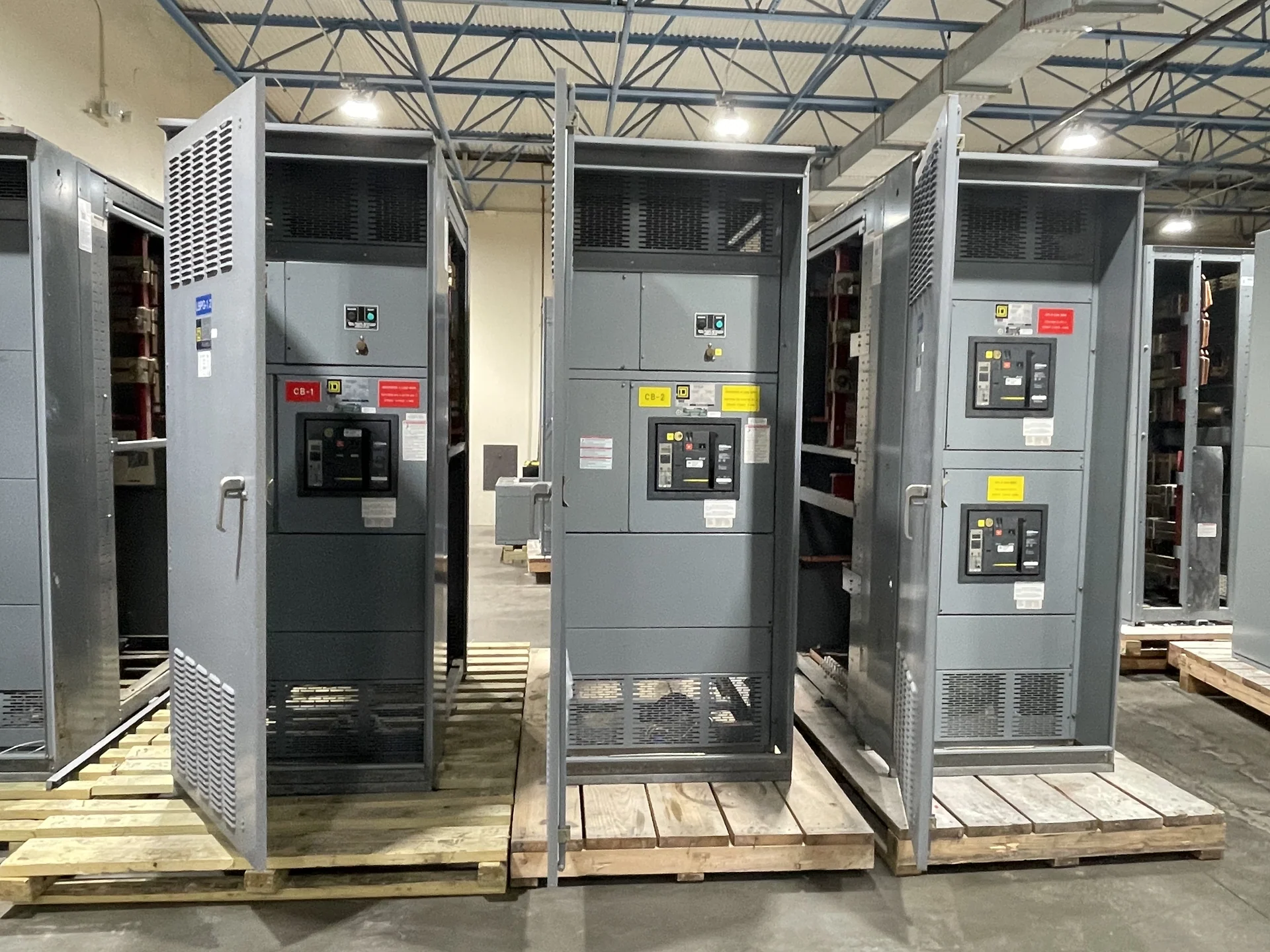
Assembly Starts with a Controlled Equipment Design
A dependable switchgear assembly begins before any enclosure is wired. The manufacturer translates the approved one-line diagram, equipment schedule, control requirements, physical dimensions, and installation interfaces into coordinated drawings. That review identifies the lineup arrangement, incoming and outgoing connections, busbar paths, protective-device positions, metering locations, doors, barriers, and access points. It also exposes conflicts early, such as a cable entry that interferes with a device or a control component placed where maintenance access is limited. Switchgear Builders combines U.S. manufacture of new electrical switchgear with custom specifications, American components, and nationwide shipping; the applicable scope remains defined by each project package.
Enclosure and Internal Layout Coordination
Fabricated enclosures provide the structure that keeps power and control components organized, accessible, and aligned with the installation. Assembly planning considers overall dimensions, mounting surfaces, removable covers, hinged doors, ventilation provisions, cable compartments, grounding points, and the route required to move the finished sections into position. Internal separation and clearances must follow the selected equipment design and applicable project requirements rather than a generic layout. A useful review compares approved drawings with field constraints, including room working space, conduit approach, floor or wall interfaces, lifting needs, and the direction in which doors must open.
Busbars, Connections, and Mechanical Fit
Busbars form the main conductive paths through many switchgear lineups, so their fabrication and installation require disciplined identification, support, joint preparation, and torque control. The assembly team positions conductors and supports according to the engineered arrangement, preserves specified electrical clearances, and verifies that connections are accessible for inspection. Incoming lugs, feeder terminals, neutral conductors, and grounding provisions must match the project interface and conductor plan. Mechanical checks are equally important: doors, barriers, drawout interfaces where specified, and covers should align without forcing parts into place or obscuring labels and service points.
Protective Devices and Control Wiring
Circuit breakers, switches, fuses where specified, meters, relays, terminal blocks, and control components are installed only after their ratings, physical footprints, connection points, and intended functions are reconciled with the drawings. Control wiring benefits from consistent routing, durable identification, suitable termination, and deliberate separation from power conductors where the design requires it. Interlocks and source-control sequences deserve a point-by-point review because a correctly mounted device can still be connected incorrectly. The project test plan should identify which indications, trips, permissives, alarms, and remote interfaces are expected to operate and what evidence will be recorded.
Inspection and Project-Specific Verification
Inspection is a series of checks, not a single visual glance at a completed lineup. Manufacturer personnel can compare component identities against approved bills of material, inspect fasteners and terminations, verify wire markers, review bus supports, confirm enclosure dimensions, and check that documentation matches the built assembly. Electrical checks may include continuity, insulation-related checks, polarity or phasing confirmation where applicable, and functional operation defined by the agreed test plan. Acceptance criteria, witness points, test instruments, and recorded results should be established with the responsible engineering and procurement teams. UL 891 applicability, including any project-specific listing requirement, must be confirmed for the particular assembly rather than assumed.
Documentation, Shipment, and Site Coordination
A finished switchgear assembly is easier to receive and install when its documentation and logistics are coordinated with the physical build. The project package may identify approved drawings, device schedules, wiring information, terminal references, test records, lifting points, shipping splits, section weights, and receiving checks. Before shipment, the buyer, electrical contractor, and qualified rigging personnel should agree on access, unloading equipment, storage conditions, sequence of placement, and responsibilities for field connections. Nationwide shipping can support U.S. projects, but destination details, packaging, freight terms, configuration, and project-specific availability must be reviewed before a delivery plan is established.