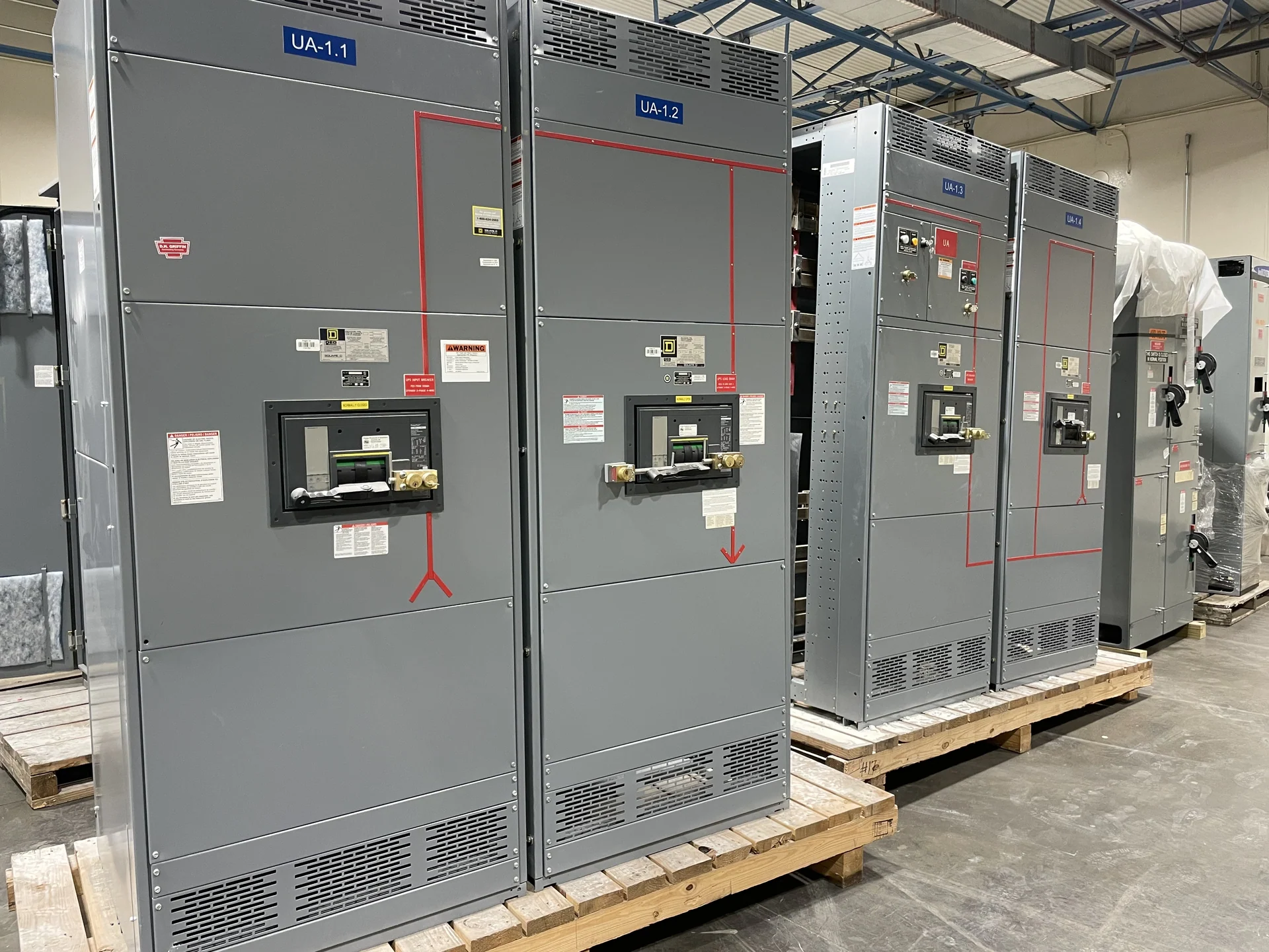
Start with the electrical arrangement
A coordinated switchgear electrical assembly begins with the system one-line diagram, load schedule, available fault current, source arrangement, and installation environment. Those inputs establish how the bus, mains, feeders, protective devices, metering, and controls must relate to one another. Our American manufacturing team builds new electrical switchgear custom to specification, using American components and project-defined interfaces. Before fabrication, identify nominal voltage, phase and wire configuration, continuous current, interrupting or withstand duty as applicable, grounding method, enclosure conditions, cable entry, and the intended operating sequence. This front-end definition prevents a physically neat assembly from becoming an electrically mismatched one.
Integrate the bus and protective devices
Bus integration is more than placing conductors inside an enclosure. The design must account for conductor material, dimensions, supports, joints, clearances, barriers, termination space, and the specified short-circuit duty of the assembly. Main and feeder protective devices then need compatible frame or switch ratings, interrupting capability, connection geometry, and access for operation and maintenance. A custom builder should receive the latest device schedule and coordination assumptions rather than an early placeholder list. If a breaker, fuse, or switch changes during review, its dimensions, terminals, heat contribution, settings, and interlocks can affect adjacent compartments and the overall lineup.
Plan metering and control wiring
Metering and control wiring should be designed as part of the assembly, not appended after the power compartments are complete. Define the instruments, sensing points, transducers, control voltage, terminal blocks, wire identification, communication connections, and required separation from power conductors. The operating narrative should explain source selection, permissives, trip indications, alarms, breaker status, and any tie logic in plain language. That narrative gives the manufacturer and reviewing engineer a basis for checking wire numbers, terminal assignments, interlocks, and point-to-point continuity. It also helps the installer understand field connections without guessing which circuits are factory wired or which remain site responsibilities.
Coordinate physical layout and service access
The electrical assembly must fit the room, the shipping route, and the installation sequence as well as the electrical design. Confirm lineup width and height, shipping splits, section weights, lifting provisions, front and rear access, cable bending space, ventilation needs, door swing, and working clearances with the project team. Device placement can influence maintenance access, heat dissipation, conduit entry, and the ability to withdraw or service a component where the selected arrangement allows it. Drawings should show external dimensions, mounting points, cable entrances, field terminals, and interfaces to adjacent equipment so installers can coordinate concrete, supports, conduits, and controls before delivery.
Use inspection and testing to confirm the build
Inspection and testing should follow an agreed project plan that traces the approved drawings to the completed assembly. Useful checks may include enclosure dimensions, bus and connection workmanship, device identification, torque records where specified, wiring continuity, insulation checks where applicable, grounding paths, meter polarity, control operation, interlock behavior, and simulated source or trip sequences. The acceptance criteria, test instruments, witness points, and documentation format belong in the project requirements; they should not be assumed from a generic description. If UL 891 is identified for a particular switchboard project, its applicability, construction requirements, and any project-specific listing or verification must be confirmed before the design is finalized.
Prepare a complete manufacturer inquiry
A useful inquiry for new switchgear electrical assembly should include the one-line diagram, load and feeder schedule, equipment ratings, available fault-current information, enclosure and environmental requirements, dimensions, cable-entry direction, device list, metering schedule, control schematic or sequence, communication needs, field connection points, drawing standards, inspection expectations, destination, and shipping constraints. Mark open decisions clearly so assumptions can be priced and reviewed separately. Switchgear Builders manufactures new equipment in the United States, supplies American components, and ships nationwide; project-specific engineering, component selection, documentation, and freight details still require confirmation before an order is finalized.