Start With the Equipment Scope
A UL 891 switchboard assembly begins with a clear definition of the equipment being designed, not with a generic label applied to every distribution lineup. The project team should identify nominal voltage, continuous current, short-circuit current rating, service or feeder role, number of sections, incoming and outgoing devices, bus arrangement, enclosure environment, and installation location. A one-line diagram, load information, available fault current, grounding method, utility requirements, and the governing project specification give the manufacturer a usable technical foundation. Applicability of UL 891, along with any project-specific listing or evaluation requirement, must be confirmed for the actual assembly before design decisions are finalized.
Translate Ratings Into a Buildable Layout
Once the electrical scope is established, the layout must connect ratings to physical construction. Engineers and installers should review section dimensions, cable entry and exit, bending space, device access, barriers, bus supports, neutral and ground provisions, metering space, control compartments, and the movement path into the electrical room. A compact arrangement may reduce footprint while making conductor termination or maintenance access more difficult; a larger lineup can simplify access but affect room clearances and shipping sections. The final arrangement should be checked against the project drawings, working-space requirements, lifting plan, and field installation interfaces rather than copied from an unrelated assembly.
Control Materials and Assembly Work
Material selection and workmanship are central to a consistent switchboard manufacturing process. The build package should identify enclosure material and finish, bus conductor material, insulating supports, barriers, protective devices, terminals, labels, hardware, and control components, with part data and substitutions subject to engineering review. Fabrication records should connect cutouts, mounting points, bus preparation, joints, and torque instructions to the approved drawings. During assembly, technicians can verify alignment, clearances, conductor identification, mechanical fasteners, bonding paths, door operation, and device operation as applicable. These checks help detect a drawing or fabrication issue before the equipment is packaged for shipment.
Define Verification Before Production
A useful verification plan separates what is inspected from what is electrically or functionally tested. Dimensional inspection can confirm section sizes, device locations, bus alignment, cable access, labels, and lifting provisions. Electrical checks may include continuity, bonding-path review, insulation-related measurements, and control-circuit operation when those checks are appropriate to the specified assembly and test plan. Protective-device settings, metering functions, interlocks, source sequences, and remote interfaces require inputs from the engineer of record and the approved control narrative. Acceptance criteria, instruments, witness points, and record formats should be agreed before production, because UL 891 applicability does not replace project-specific engineering review or a documented test plan.
Coordinate Drawings and Project Evidence
Submittal coordination should make the proposed assembly understandable to the people who will approve, install, operate, and maintain it. A practical package may include the one-line diagram, elevation and plan views, section details, nameplate information, device schedules, wiring diagrams, terminal plans, bus data, enclosure details, shipping splits, and installation notes. The package should identify assumptions that still need confirmation, such as utility metering, cable sizes, control power, field connections, environmental exposure, and the required evidence for any UL 891 project condition. American components and custom fabrication can support a direct manufacturer conversation, but component origin, construction details, and any listing status remain matters to confirm for the specific bill of material and project.
Plan Delivery Around the Finished Assembly
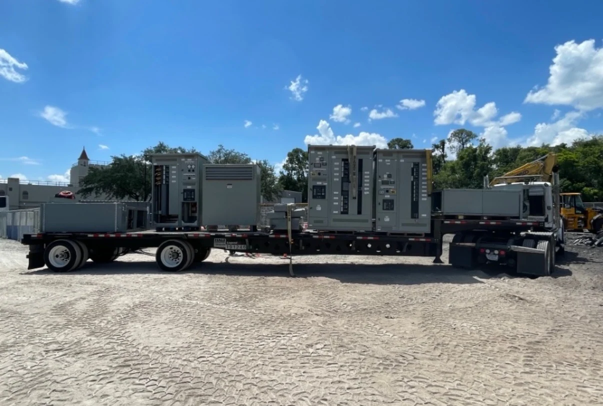
The final stage connects factory completion with safe receiving and installation. Before shipment, the team should reconcile approved drawings, inspection records, test results, loose-shipped parts, lifting points, section weights, packaging protection, and destination access. The electrical contractor or qualified rigging team should verify unloading equipment, doorway dimensions, floor capacity, storage conditions, and the sequence for setting and joining sections. Switchgear Builders manufactures new electrical switchgear in the United States, builds custom equipment to project specifications with American components, and supports nationwide shipping coordination; project-specific configuration, documentation, freight terms, and transit expectations should be confirmed in the quotation and order review.