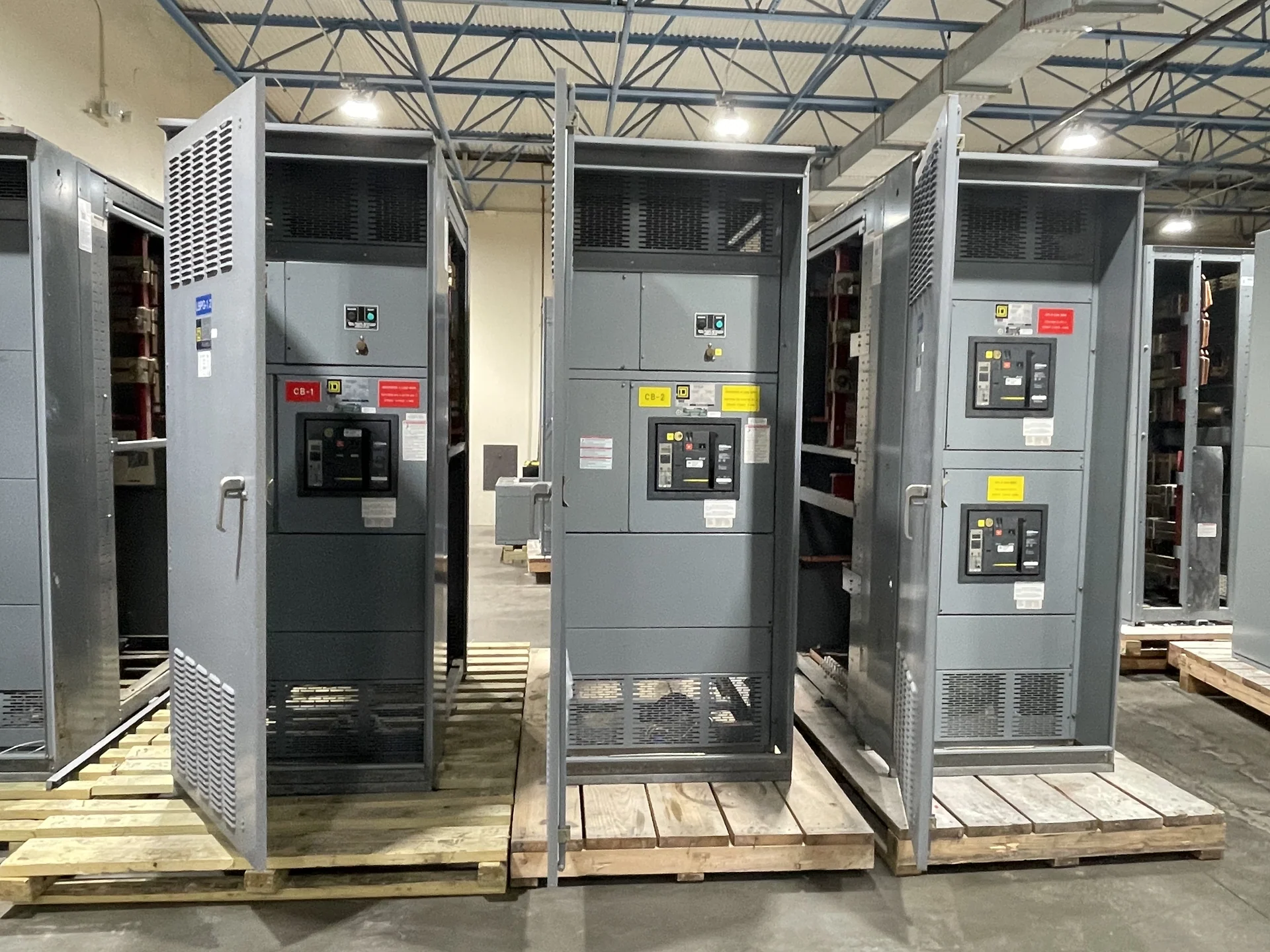
Control Wiring Starts with the Operating Sequence
Switchgear control wiring is the circuit-level link between a lineup's power devices and the people, relays, meters, sensors, and automation systems that direct its operation. A sound design begins with an agreed operating sequence: which source may close, what conditions permit a breaker to operate, how a trip is initiated, and what indications must be visible. Engineers should provide the one-line diagram, elementary or schematic diagrams, source logic, control voltage, device list, and required permissives before fabrication. Those inputs let an American manufacturer build new electrical switchgear custom to specification rather than treating terminal connections as an afterthought.
Separate Power and Control Functions
Segregation of control wiring from power conductors supports orderly construction, inspection, troubleshooting, and maintenance. The layout should account for physical routing, barriers, wireway space, bending room, heat exposure, and the relationship between field terminals and internal devices. Power conductors carry the distribution duty; control conductors convey commands, status, trip circuits, interlocks, and measurement signals, so their paths and terminations deserve deliberate treatment. The applicable project standards and equipment construction requirements determine the exact separation approach. Where UL 891 may apply, its applicability and any project-specific listing or verification must be confirmed for the particular assembly rather than assumed.
Terminal Identification and Field Interfaces
Terminal identification turns a wiring diagram into an installable field interface. A project package should define terminal numbering, wire labels, terminal-block grouping, spare points, shield or drain-wire treatment where relevant, and the destination of every incoming and outgoing circuit. Marking should remain consistent across schematics, panel layouts, interconnection drawings, and inspection records. Clearly identified source, load, alarm, trip, close, permissive, and communications interfaces help the electrical contractor coordinate the actual field connections. Before release, compare the terminal plan with cable schedules, conduit routes, control-panel requirements, and the installing engineer's designated responsibilities.
Device Circuits and Interlocks
A practical control-wiring review traces each device circuit from its source through protective elements, contacts, coils, terminals, and return path. Breaker close and trip circuits, spring-charged or position indications, door or compartment interlocks, shunt functions, undervoltage functions, lockout contacts, and auxiliary contacts can each affect the operating sequence. The manufacturer and project team should identify normal states, fail-safe intent, momentary versus maintained signals, and any required electrical or mechanical interlock. Hypothetical example: a tie device might be permitted to close only after both main devices report the defined open condition; the actual logic must come from the approved project design.
Inspection, Testing, and Documentation
Control wiring quality is checked through more than visual appearance. A project-specific inspection and test plan can call for conductor identification checks, point-to-point continuity, terminal torque verification, insulation or dielectric checks where appropriate, control-voltage verification, contact-state confirmation, and functional simulation of the approved sequence. Test limits and acceptance criteria should be established by the responsible engineer and applicable requirements. Recorded redlines, final schematics, terminal schedules, device data, and test results give the installer and owner a coherent reference. These records also make later troubleshooting more disciplined because each tested circuit has a traceable destination.
Planning a Custom Control-Wiring Package
For a quote or design review, send the manufacturer the project location, equipment type, one-line diagram, control schematics, nominal control voltage, device schedule, source and tie logic, metering or communications interfaces, enclosure and access constraints, cable-entry information, and documentation expectations. Identify who supplies external relays, protection settings, network equipment, field cables, and final terminations. Switchgear Builders manufactures new electrical switchgear in the United States, uses American components for its builds, and supplies equipment with nationwide shipping; project-specific component details, scope, and shipping arrangements should be confirmed in the quotation.