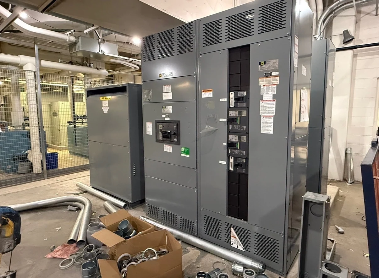
What a Main-Tie-Main Arrangement Does
Low-voltage main-tie-main switchgear divides a distribution lineup into two bus sections, each supplied through a main protective device, with a tie device connecting the sections. In normal operation, both mains may be closed and the tie open, allowing each source to serve its assigned loads. A project may instead specify a different normal state, such as one source carrying both sections while the other remains available. The useful design question is not simply whether a tie exists, but which sources, loads, and operating states the electrical system must support. A new custom lineup can be built from the approved one-line diagram, equipment dimensions, control requirements, and installation interfaces.
Define Sources, Loads, and Operating States
Before requesting a low-voltage main-tie-main switchgear quote, document the source identity and electrical data for each main: nominal voltage, phase and wire arrangement, frequency, grounding method, continuous current, available fault current, and upstream protection. Identify the feeders on each bus section, including essential loads, large motors, transformers, distributed generation, or other equipment that can change fault or load-flow conditions. Then describe normal, alternate, maintenance, and abnormal states in plain language. A hypothetical facility might operate with both mains closed during ordinary service, open one main for maintenance, and close the tie only after an approved transfer sequence. Those states give the manufacturer and engineer a concrete basis for custom switchgear design.
Interlocking and Transfer Logic
Interlocking prevents an operating sequence from creating an unintended connection between sources or energizing an isolated section. The required arrangement may use mechanical interlocks, key interlocks, electrically supervised permissives, protective-relay logic, or a coordinated combination, depending on the sources and project rules. Specify which devices may close together, what conditions block a close command, how a loss of source is detected, and how manual operation differs from automatic transfer. If sources could be paralleled, the design requires an explicit engineering decision about synchronization, protection, controls, and operating authority; a basic main-tie-main arrangement should not be assumed to permit paralleling. Control power, remote indications, alarm contacts, and local-versus-remote selector behavior should also be shown on the control drawings.
Ratings and Physical Configuration
Main-tie-main selection must align the assembly with calculated load current, protective-device ratings, available fault current, bus bracing requirements, and the project voltage class. The mains and tie are not automatically interchangeable: their continuous-current duties, interrupting requirements, trip functions, and coordination settings may differ. Physical planning is equally important. Confirm lineup width and height, cable entry, conductor bending space, working clearances, ventilation, lifting provisions, door swing, maintenance access, and the route from unloading point to the electrical room. For a custom build, provide the approved one-line, equipment schedule, floor plan, feeder conductor details, control schematic, and site constraints so the proposed electrical distribution equipment can be checked against the actual installation rather than a generic arrangement.
Protection, Coordination, and Documentation
Protective coordination should be reviewed across both source paths, the tie, and downstream feeders. A tie that changes which source supplies a bus can alter fault contribution, available short-circuit current, and the time-current relationship between devices. The engineer should establish trip-unit functions, settings, zone or ground-fault requirements where applicable, and the permitted operating sequence before final drawings are released. Ask for documentation that matches the ordered configuration, such as a one-line diagram, elevations, wiring diagrams, device schedules, terminal information, nameplate data, and agreed inspection or test records. If a project invokes UL 891, confirm its applicability, construction requirements, and any project-specific listing or verification with the responsible parties for the particular lineup.
Ordering New Custom Switchgear from the Manufacturer
Switchgear Builders manufactures new electrical switchgear in the United States, builds custom equipment to project specifications, uses American components, and supplies equipment with nationwide shipping. For a useful inquiry, send the one-line diagram, source and load information, desired main-tie-main operating sequence, interlocking philosophy, enclosure environment, dimensions, controls, metering, documentation expectations, destination, and required commercial terms. The resulting scope can then identify inclusions, exclusions, assumptions, review points, and shipping responsibilities without treating an unconfirmed feature as automatic. A customer buying new switchgear should coordinate the final design with the engineer of record, electrical contractor, utility or authority when applicable, and qualified personnel responsible for installation and commissioning.