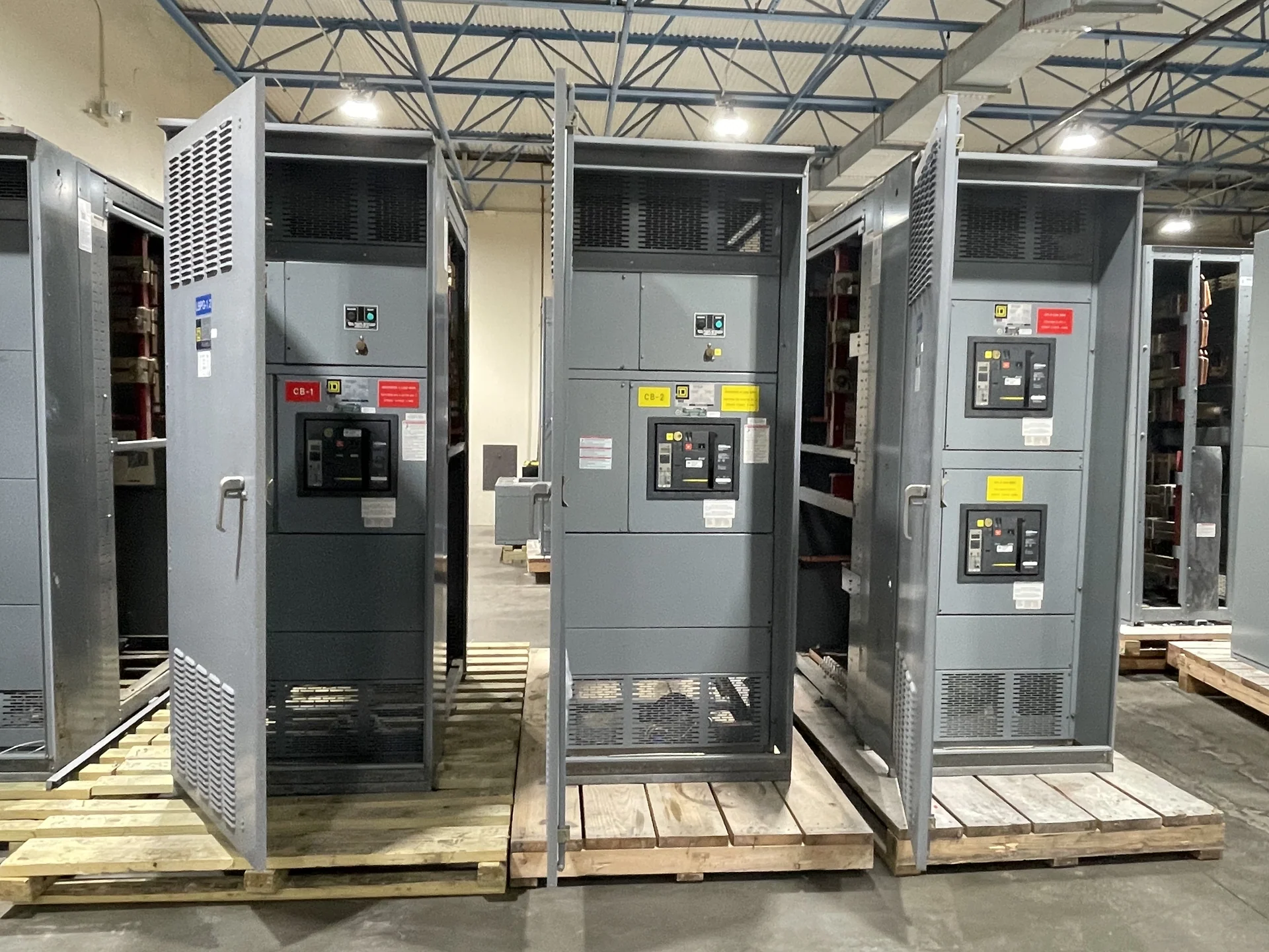
What a Medium-Voltage Main-Tie-Main Arrangement Does
Medium-voltage main-tie-main switchgear places two incoming source sections and a bus-tie device into one coordinated distribution arrangement. Each main connects a source to its bus section, while the tie can connect those sections under a defined operating sequence. This topology can support source transfer or sectionalizing decisions, but it is not automatically a redundant system. Engineers must establish whether both sources may operate simultaneously, whether the tie is normally open, and which loads may be supplied during each switching state. Switchgear Builders manufactures new electrical switchgear in the United States, custom to specification with American components and nationwide shipping; the final arrangement remains dependent on the project's electrical study, equipment requirements, and installation interfaces.
Define Sources, Loads, and Operating States
A useful medium-voltage main-tie-main switchgear selection begins with a single-line diagram that identifies source names, nominal system voltage, phase and frequency, grounding method, feeder destinations, transformer connections, and expected load transfer paths. Describe normal, alternate, maintenance, and abnormal states in plain language, then show which main and tie positions are permitted in each state. The specification should identify whether paralleling is prohibited, allowed only briefly, or intended as a controlled operating mode. Include utility or generator interface requirements, synchronism conditions where applicable, and the authority responsible for approving the switching sequence so the manufacturer can translate the intent into a buildable control scheme.
Interlocking Is a Design Requirement, Not an Add-On
Source interlocking prevents an operator or control circuit from creating an unapproved connection between sources. The exact logic may use mechanical key interlocks, trapped-key arrangements, electrical permissives, breaker position contacts, control relays, or a coordinated combination. Selection should account for drawout or fixed device construction, local and remote control, emergency operation, test positions, grounding devices, and the consequences of control power loss. A clear truth table is especially valuable: list each main and tie state, the switching action requested, the permissive conditions, and the lockout result when a condition is absent. This exposes ambiguous sequences before fabrication and gives installers and operators a shared reference.
Coordinate Protection Across Both Bus Sections
Protection coordination for a main-tie-main lineup must consider fault current from every connected source and every permitted operating state. Provide available fault current at each incoming source, transformer impedance information, feeder contributions, grounding details, and the intended protective-device family to the engineer performing the study. Main and feeder functions should be reviewed together so a downstream fault does not unnecessarily trip an upstream main or tie. If the tie can be closed, evaluate the resulting duty, relay sensing, directional behavior where relevant, and changes in time-current relationships. The final settings, instrument-transformer requirements, and trip logic should come from the project protection study rather than a generic lineup assumption.
Plan Physical, Control, and Installation Interfaces
Electrical performance is only one part of a practical medium-voltage main-tie-main switchgear package. Confirm indoor or outdoor application, enclosure requirements, cable entry direction, termination space, bus orientation, lineup dimensions, access paths, lifting provisions, control-power source, communications, metering, and grounding connections. The room layout should account for working clearances, maintenance access, ventilation, arc-flash study inputs, and the movement route from receiving to the final position. Identify who supplies cable terminations, relaying, auxiliary power, remote annunciation, and field wiring. These details reduce late changes and help a manufacturer prepare drawings that can be reviewed by the engineer, contractor, utility, and facility team.
Prepare a Custom Manufacturer Quote Request
For a custom quote, send the latest single-line diagram, equipment schedule, source data, fault-duty information, protection study criteria, control sequence, interlock narrative, physical arrangement, environmental conditions, documentation list, destination, and requested commercial terms. State whether the project requires a particular standard or construction approach, and ask the manufacturer to identify which requirements need clarification before release for fabrication. UL 891 may apply to some low-voltage switchboard projects, but its applicability does not automatically extend to medium-voltage main-tie-main switchgear; confirm the governing standard, evaluation path, and any project-specific listing requirement with the responsible engineer. Switchgear Builders can build and supply new equipment to the approved scope, with shipping coordination based on the destination and project requirements.