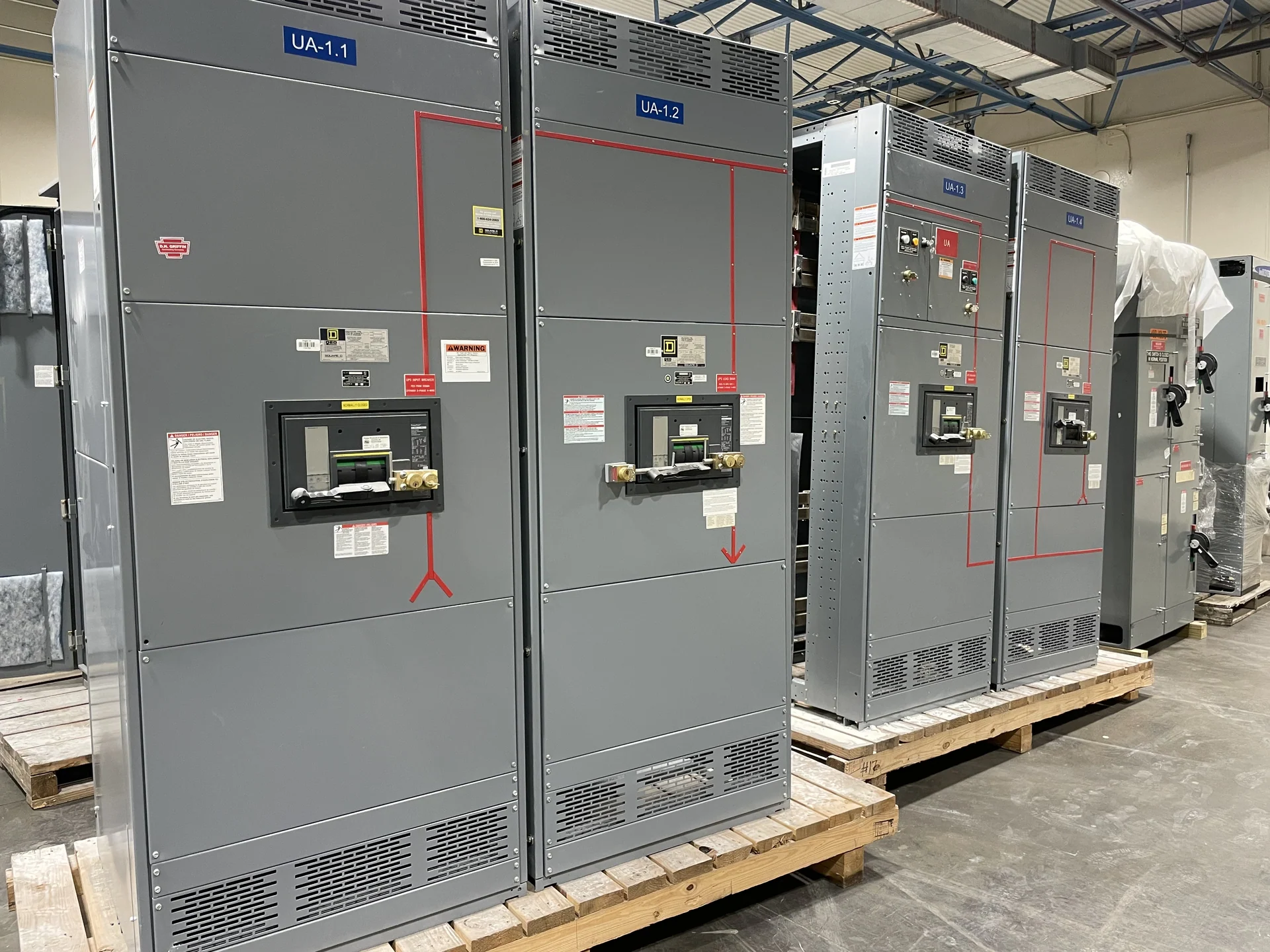
How a Main-Tie-Main Arrangement Works
A main-tie-main lineup divides a switchgear bus into two sections, with a main protective device connected to each incoming source and a tie device connecting the sections. In normal operation, both mains may be closed and the tie open, allowing each source to supply its assigned bus section. An alternate sequence can keep one main open while the tie closes, subject to the system design. This guide to main-tie-main distribution is not a universal operating prescription: the electrical engineer must define source relationships, grounding, load allocation, interlocks, and permissible switching states for the specific installation. The arrangement is useful when a project needs flexible source management, but flexibility adds coordination work.
Define Sources, Loads, and Normal States
Start electrical distribution planning with a current one-line diagram rather than with a preferred breaker layout. Identify each utility, generator, transformer, or other source; its nominal voltage, phase arrangement, grounding method, available fault current, and intended contribution. Then assign feeders and loads to each bus section, noting essential loads, large motors, nonlinear loads, and any generation that can backfeed. The design should state whether sources may operate in parallel, whether a closed-transition transfer is contemplated, and what conditions require the tie to remain open. A manufacturer can use these inputs to build new equipment to the approved arrangement, but source behavior and system studies remain engineering responsibilities.
Operating Sequence and Interlocking
The operating sequence explains what operators or automatic controls may do, in what order, and only after which permissive conditions are satisfied. A basic open-transition sequence might open Main 1, verify its isolated state, confirm source availability on the other section, and then close the tie; returning to normal requires an equally explicit reverse sequence. Mechanical key interlocks, electrical interlocks, control relays, breaker status contacts, and source-sensing logic can enforce selected states, but their roles must be documented rather than assumed. Review whether a failed control signal leaves equipment in a safe, identifiable state, and decide how local and remote commands interact before finalizing the control scheme.
Protection and Fault-Duty Review
Closing a tie changes current paths and can change the fault duty seen by mains, feeders, and bus sections. Protective-device interrupting ratings, continuous current ratings, short-circuit withstand requirements, ground-fault functions, and relay settings should therefore be checked for every permitted configuration, not only the normal state. A coordination study should examine source impedance, transformer data, conductor information, and downstream device curves, while an arc-flash study may evaluate incident-energy conditions and operating labels under defined scenarios. The final switchgear specification should identify the study assumptions and setting responsibilities. Main-tie-main equipment can be manufactured with project-defined devices and controls, while engineering review determines whether the complete system performs as intended.
Physical Layout and Installation Interfaces
A sound main-tie-main design also fits the electrical room and the installation process. Confirm lineup width, height, depth, front or rear access, cable-entry direction, conductor bending space, working clearances, ventilation, lifting provisions, and the route from receiving to the final location. Locate mains and tie equipment so labels, handles, indicators, test positions, and maintenance access match the operating procedure. Coordinate incoming source compartments, feeder exits, metering, control power, communications, and grounding connections with the installing contractor. Switchgear Builders manufactures new custom equipment in the United States using American components and can coordinate the documented configuration for nationwide shipment; site preparation and installation remain project-specific.
Documents and Quote Inputs
A useful request for a main-tie-main quote should include the approved one-line diagram, source and load schedules, voltage and frequency, phase and wire configuration, available fault current, continuous load calculations, enclosure environment, dimensions, cable details, metering needs, control power, interlocking narrative, and required drawings or test records. State whether UL 891 applies to the proposed assembly and ask for project-specific confirmation of applicability and any related requirements; do not treat the standard as automatic for every switchgear type. Provide destination, shipping constraints, and desired division of responsibilities. Complete inputs let the manufacturer identify assumptions, exclusions, component choices, and configuration questions before fabrication begins.