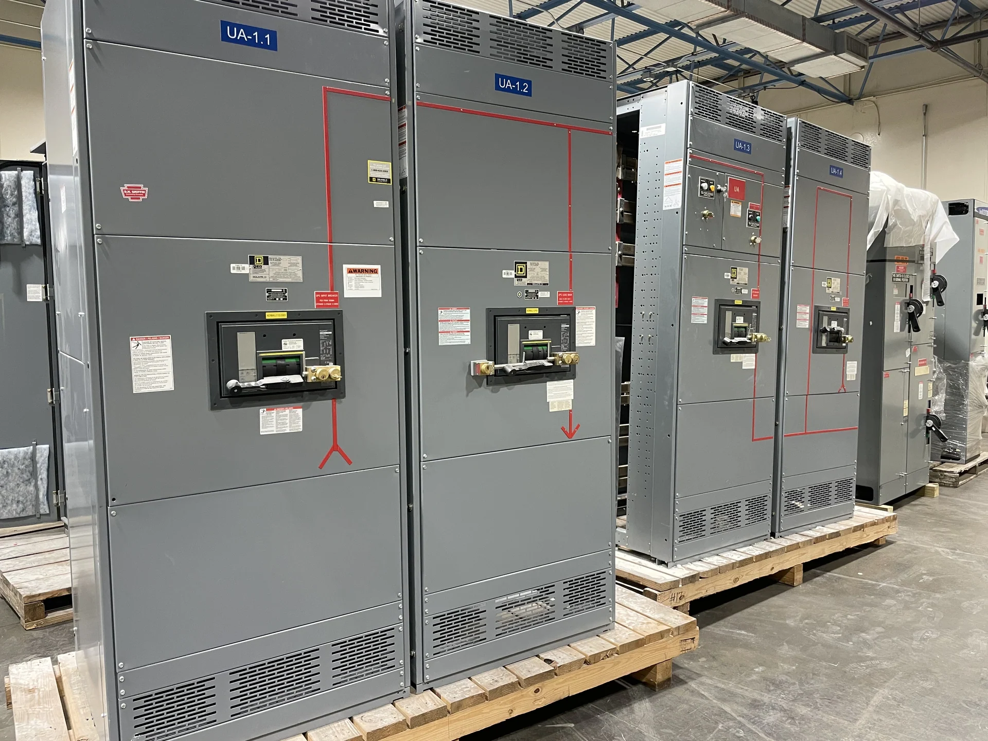
Start with the motor and system duty
A motor control center with variable frequency drives should be designed from the driven equipment and distribution system outward. Gather motor horsepower, voltage, phase, full-load current, starting requirements, duty cycle, speed range, bypass preferences, and the number of motors before selecting a lineup. The process load may require several operating speeds, while another application may need torque at low speed or frequent acceleration. Those differences affect drive sizing, feeder grouping, protective devices, ventilation, control interfaces, and spare space. A useful electrical schedule also identifies incoming source data, available fault current, grounding method, short-circuit requirements, environmental conditions, and whether the center serves one process or multiple production areas. Switchgear Builders manufactures new custom equipment in the United States, using American components and shipping nationwide; each proposed assembly remains subject to project engineering and component confirmation.
Arrange the lineup for heat and service access
Variable frequency drives convert power electronically and can add concentrated heat inside an MCC enclosure. A practical layout considers drive losses, ambient temperature, enclosure conditions, spacing between heat-producing compartments, airflow paths, and the room's ventilation plan. Do not treat an enclosure dimension as a substitute for a thermal review: drive arrangement, bypass hardware, line reactors, transformers, and control power devices can change the heat profile. Service access matters just as much. Place disconnects, terminals, keypads, network interfaces, and removable sections where qualified personnel can reach them without obstructing adjacent equipment. Provide a documented section arrangement, cable-entry direction, lifting or shipping split assumptions, and clear responsibility for field ventilation and installation interfaces.
Address harmonics before finalizing components
Drives can draw current in a way that differs from a basic linear motor load, so harmonic effects belong in the design conversation rather than in commissioning surprises. Ask the electrical engineer to establish the expected drive population, operating mix, source strength, transformer arrangement, and any limits or study requirements that apply to the facility. Depending on that review, the lineup may need specified input reactors, filters, multipulse arrangements, or other mitigation selected by the project team; no option should be assumed from the phrase VFD MCC alone. Consider interaction with generators, capacitors, UPS equipment, metering, and sensitive controls. The equipment schedule should state which harmonic-related components are included, where they are installed, and what data the manufacturer must receive.
Coordinate protection, bypass, and controls
Each drive section needs a clear relationship between the branch disconnect, overcurrent protection, motor protection, drive input, output conductors, and the control system. Define whether a bypass is required, what operating states it must support, and whether bypass operation changes motor protection or interlocking. A main device, feeder arrangement, control transformer, pilot devices, and network components should be coordinated with the one-line diagram and sequence of operations. Specify permissives, run commands, fault indication, local-versus-remote control, emergency stops, and loss-of-communication behavior in plain language. Review drive manufacturer installation requirements, motor cable length, grounding, and compatibility with the intended motor before release. A custom manufacturer can use this information to align the enclosure, bus, devices, wiring, and documentation rather than forcing the project into a generic arrangement.
Plan maintainability and documentation
An MCC is easier to operate when the physical lineup and its documents tell the same story. Identify section labels, feeder names, terminal designations, control wire numbers, network addresses or node conventions, spare provisions, and the location of fuses or other replaceable parts. Decide how drive parameters, alarm definitions, interlocks, and bypass instructions will be recorded; those items should be coordinated with the controls contractor and the facility's maintenance practices. Include the desired drawing set, wiring diagrams, device schedules, layout dimensions, nameplate information, and project-defined test records in the quote request. Confirm lifting points, shipping sections, receiving access, and field connections early, because a technically correct lineup can still create installation difficulty if its path into the electrical room is overlooked.
Prepare a complete VFD MCC quote request
For a manufacturer quote, submit the latest one-line diagram, motor schedule, load list, control schematic or sequence, room and lineup dimensions, incoming and outgoing cable information, environmental conditions, fault-duty data, and any owner or engineer specifications. Mark required drive brands or acceptable alternatives only when the project permits them, and identify communications, metering, bypass, spare, and future-expansion expectations separately from mandatory scope. State whether the equipment is indoors or outdoors, how it will be split for shipment, and who supplies field-installed conduit, network wiring, ventilation, and commissioning services. Switchgear Builders can review a request for a new custom motor control center and nationwide shipment. Confirm configuration, component availability, applicable standards, and any project-specific listing or UL 891 applicability before finalizing the order.