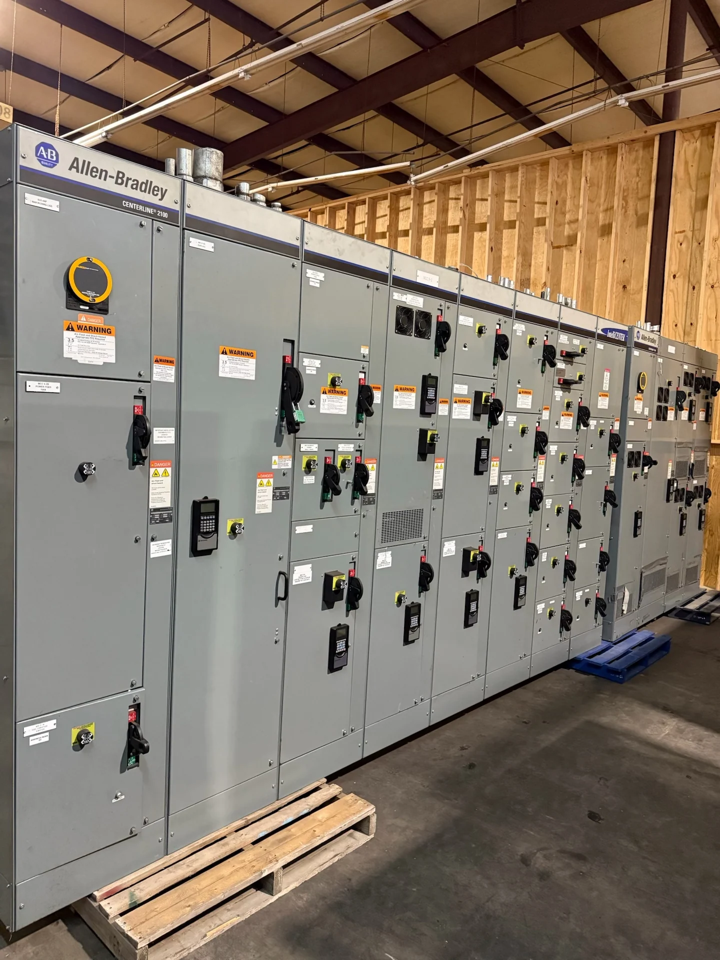
What Pad-Mounted Sectionalizing Switchgear Does
Pad-mounted sectionalizing switchgear divides an outdoor distribution circuit into controllable sections, allowing qualified personnel to isolate a feeder segment while keeping the operating sequence clear for the rest of the system. The equipment is typically installed at a defined transition point between underground circuits, transformers, or other distribution assets. A useful specification starts with the circuit arrangement, normal and alternate source paths, switching duties, grounding method, and the operating philosophy approved by the project engineer and utility where applicable. The design should also identify which switching actions are routine, which are emergency steps, and what information operators need at the enclosure.
Define the Sectionalizing Arrangement
The number and arrangement of ways should follow the actual one-line diagram rather than a generic enclosure size. Identify incoming and outgoing conductors, normally open or normally closed points, transformer connections, fuse or interrupter functions, and any provisions for future feeders. The design team should also state whether switching is manual or motor-operated, which compartments require visible position indication, and how interlocks or key exchanges are expected to control the operating sequence. These details prevent an outdoor lineup from being configured with more or less switching capability than the distribution plan requires. Include phase identification, cable termination preferences, and labeling conventions early enough for drawings to show the intended field workflow.
Verify Electrical Ratings and Protection
Voltage class, continuous current, short-circuit duty, load-interruption capability, insulation requirements, and grounding configuration must be established from the system study and equipment specification. Sectionalizing equipment is not selected by nominal voltage alone: available fault current, transformer impedance, feeder length, source contribution, and protective-device coordination can change the required design. If fuses, switches, vacuum interrupters, relays, sensors, or control power are part of the concept, their duties and interfaces should be reviewed together so that isolation and protection work as intended. Confirm phase sequence, frequency, neutral treatment, and any communications or remote-control requirements before final device selection.
Plan the Outdoor Enclosure and Site Interface
A pad-mounted assembly must fit the civil and electrical conditions at its installation point. Confirm the pad dimensions, cable entry locations, bending space, door swing, operating-side clearances, equipment access, drainage, grounding connections, and separation from traffic or other site hazards. Enclosure construction and environmental provisions should be tied to the exposure described by the project, including moisture, corrosion, temperature, and access-control concerns. The foundation, conduit plan, lifting method, and field termination sequence should be coordinated before fabrication drawings are approved. Site photographs, civil details, and a clear route from delivery vehicle to foundation can expose conflicts that a one-line diagram cannot show.
Build a Project-Specific Equipment Package
Switchgear Builders manufactures new electrical switchgear in the United States and can develop a custom pad-mounted sectionalizing arrangement around the supplied electrical and physical requirements. American components can be incorporated where they fit the approved specification, while each device, material, and origin expectation should be identified in the quote and submittal review. Provide the one-line diagram, system data, protection study inputs, dimensions, control narrative, site conditions, utility criteria, and documentation schedule so the manufacturer can identify assumptions before building. Ask for drawings that make assumptions visible, including compartment functions, cable access, nameplate data, and the relationship between operating handles and the approved sequence.
Coordinate Testing, Delivery, and Field Work
A practical order package defines drawing approvals, inspection points, electrical checks, functional demonstrations, nameplate information, wiring diagrams, and recorded test results before production begins. Any request involving UL 891 should be treated as project-specific: confirm whether the standard applies to the proposed assembly and separately confirm the required construction, evaluation, and documentation. For nationwide shipping, provide the destination, site access limits, delivery contact, unloading responsibility, shipping split needs, lifting points, and receiving inspection plan so the new equipment arrives with a coordinated path from freight delivery to installation. The installer should reconcile shipping sections, terminations, grounding, and field checks with the approved drawings before energization.