Start With the Utility Interface
Service-entrance switchgear sits at the boundary between a utility source and a facility distribution system, so selection begins with the authority having jurisdiction and utility requirements rather than enclosure size alone. Identify the service voltage, phase and wire arrangement, grounding method, service disconnect configuration, metering approach, available fault current, and connection responsibilities. Utility standards can affect compartments, sealing provisions, instrument transformers, access, and approval steps. A useful equipment inquiry also states whether the assembly is the sole service entrance or one of several sources. Switchgear Builders manufactures new electrical switchgear in the United States, custom to project specifications, using American components and offering nationwide shipping; project documents should define the required scope.
Define the Main Disconnect and Feeder Arrangement
The service disconnecting means must be coordinated with the intended distribution topology and operating procedure. Describe the number and arrangement of main devices, feeder breakers or switches, bus sections, tie provisions, and any required interlocking. A main-tie-main concept, for example, raises questions about normal source operation, transfer steps, source separation, and whether the tie is manually or automatically operated; it should not be assumed from a preferred product label. Document device functions, trip or fuse characteristics, compartment access, cable entry, and termination space so the manufacturer can translate the one-line diagram into a buildable lineup. Confirm every operating sequence through the responsible electrical engineer.
Coordinate Metering and Service Documentation
Metering details deserve early coordination because utility-owned and customer-owned equipment may occupy different compartments and follow different access rules. Provide the utility metering standard, meter type, instrument-transformer requirements where applicable, test-switch or terminal provisions, sealing expectations, conduit routing, and responsibility for supplying each device. The equipment schedule should distinguish revenue metering from customer monitoring, since they can have different accuracy, wiring, and communication needs. Include a current one-line diagram, load schedule, service calculations, physical arrangement, and utility comments with the quote request. These inputs reduce revisions and help align drawings, labeling, wiring, and field connections before new equipment is released for fabrication.
Check Fault Duty and Protection Coordination
Service-entrance switchgear selection must account for the utility contribution, transformer characteristics, motor and generator sources, and any other source that can raise available fault current. Supply the calculated available fault current at the service point and identify the required short-circuit current rating or withstand duty for the assembly, along with interrupting ratings for individual protective devices. Coordination review should compare time-current behavior from the service device through downstream feeders, while the engineer evaluates selective coordination, arc-flash implications, grounding, and settings. Ratings cannot be inferred from amperage alone; voltage class, device type, bus construction, enclosure arrangement, and project-specific studies all matter.
Plan the Physical Installation
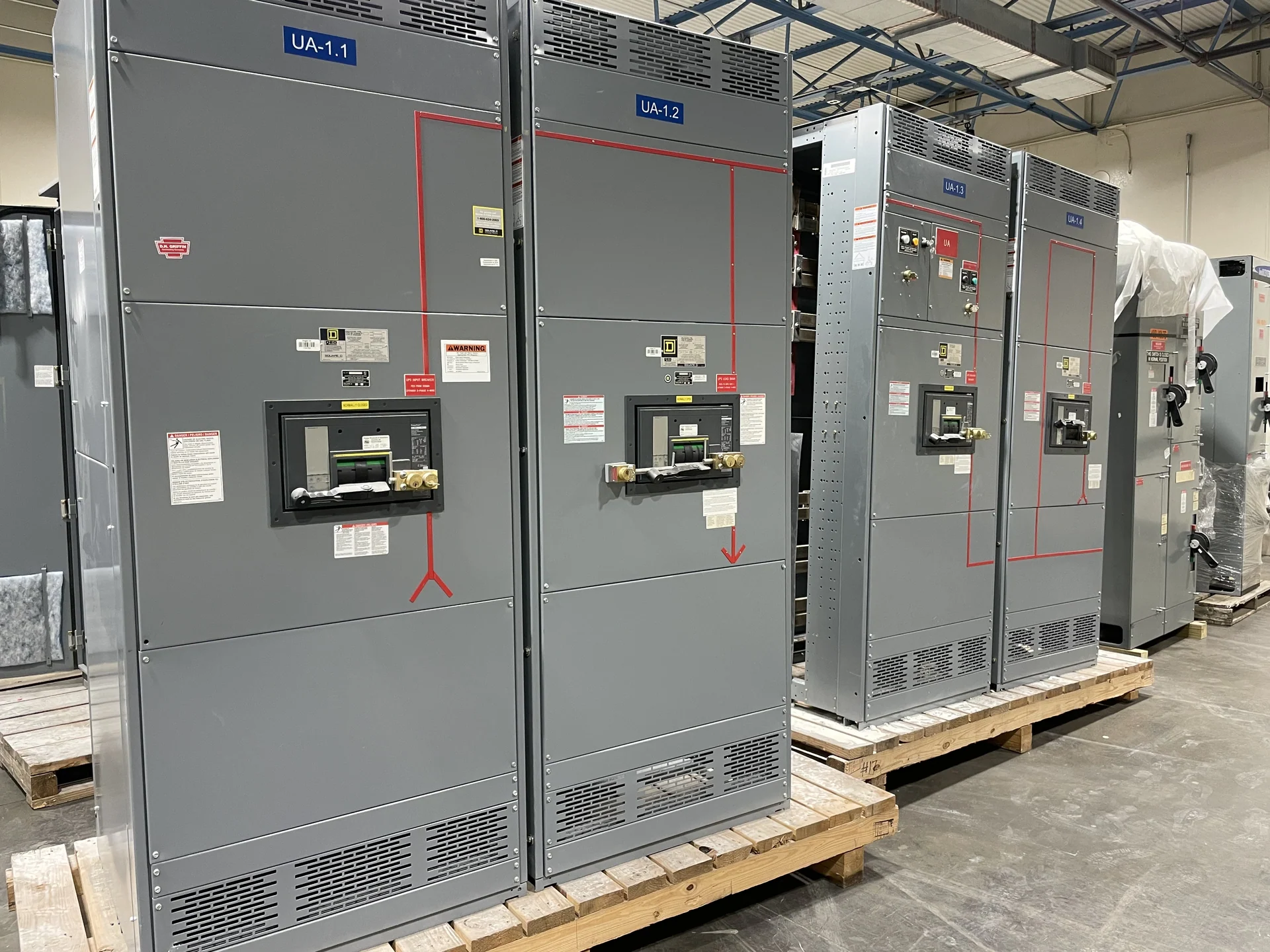
A technically suitable lineup can still create field problems if its physical interfaces are incomplete. Provide available room dimensions, equipment orientation, working clearances, overhead or underfloor routing, cable bend requirements, termination heights, wall or floor penetrations, and the movement path from receiving to the electrical room. State indoor or outdoor exposure, enclosure expectations, elevation or environmental conditions, and any seismic anchorage criteria that the project documents require. New custom switchgear should also show lifting points, shipping splits, section weights, door swing, maintenance access, and nameplate information. Coordinate these details with the installer and qualified site professionals before final drawings are approved.
Build a Complete Manufacturer Inquiry
A strong service-entrance switchgear inquiry combines electrical, physical, commercial, and documentation requirements in one controlled package. Send the latest one-line diagram, utility criteria, load and fault studies, device schedule, metering details, control narrative, enclosure conditions, dimensions, shipping destination, and requested drawing or test records. Identify exclusions and owner-furnished components instead of leaving them implicit. If the project references UL 891, first confirm that the standard applies to the particular assembly and ask for the project-specific listing or verification requirements; applicability is not automatic for every switchgear type. Switchgear Builders can review the defined scope for a custom new-equipment quote and coordinate nationwide shipment terms around the stated destination.