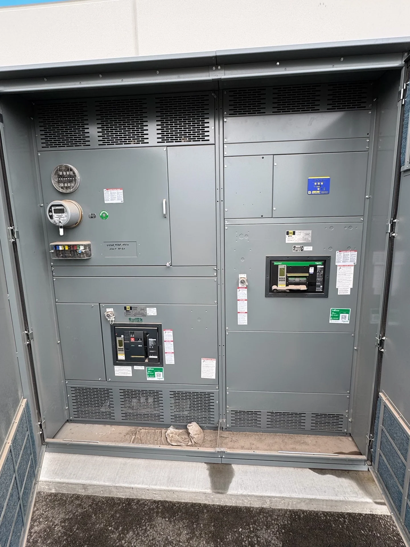
Start With the Utility Interface
Planning a service entrance begins with the boundary between the utility system and the customer-owned electrical distribution. Confirm the serving utility, service voltage, phase and wire arrangement, grounding method, metering approach, available fault current, and required service disconnect arrangement. Utility rules can govern conductor entry, meter compartments, sealing, access, and approval steps, so the equipment concept should follow current utility requirements rather than assumptions from a previous installation. A manufacturer can use these inputs to develop new custom switchgear with American components and coordinate the physical interface for nationwide shipment.
Define the Service Disconnect
The service disconnect is not simply a large main breaker; its placement, grouping, rating, accessibility, and relationship to downstream distribution all affect the design. Identify whether the project calls for a main-breaker arrangement, multiple service disconnects, a main-tie-main scheme, or another engineer-defined configuration. Review continuous current, interrupting duty, short-circuit current rating, conductor termination space, neutral switching where applicable, and operating clearances. The one-line diagram should show source conductors, mains, ties, feeders, overcurrent devices, and any interlocks clearly enough for engineering and field coordination.
Coordinate Metering and Utility Requirements
Metering requires early coordination because the utility may specify compartment dimensions, instrument-transformer provisions, meter locations, CT wiring, test switches, barriers, seals, and access responsibilities. Ask who furnishes meters and transformers, where the utility wants its equipment located, and which party reviews drawings before fabrication. Separate revenue metering from owner monitoring when the project needs both, and identify communication, remote indication, or power-quality instruments without treating them as interchangeable. A complete custom quote should identify metering scope, wiring diagrams, terminal points, and documentation responsibilities.
Plan Grounding and Bonding
Grounding and bonding decisions should be developed from the service configuration, fault-current study, utility requirements, and the authority having jurisdiction. Define the grounded conductor arrangement, equipment grounding path, bonding points, grounding electrode connection, neutral-to-ground relationship, and any separately derived source interfaces. The enclosure, doors, barriers, cable compartments, and removable sections need a practical bonding strategy that remains accessible for inspection and installation. Do not infer grounding details from nominal voltage alone; provide the electrical engineer's diagrams and written requirements so the manufacturer can reflect them in the equipment design.
Fit the Equipment to the Electrical Room
A service entrance layout must work on paper and at the job site. Establish lineup width, depth, height, shipping splits, cable entry direction, bending space, working clearances, maintenance access, ventilation needs, doors, thresholds, structural supports, and the path from unloading point to final location. Check conflicts with walls, columns, piping, fire-rated construction, and other equipment before drawings are approved. Include bus and feeder routing, termination compartments, lifting provisions, and field connection points in the layout review. These details help a manufacturer build equipment that aligns with the installation interfaces instead of forcing late field changes.
Prepare a Complete Manufacturer Inquiry
A useful inquiry for new service-entrance switchgear includes the one-line diagram, load schedule, service and distribution ratings, fault-current information, utility comments, metering requirements, grounding details, enclosure environment, dimensions, cable data, control requirements, desired shipping destination, and the drawings or standards governing the project. Also identify the installing contractor, engineer-of-record review path, preferred cable termination orientation, and whether field wiring enters from above, below, or a side compartment. Clarify who supplies lugs, meters, instrument transformers, and site hardware so the quote compares a defined scope rather than assumptions. State whether UL 891 may apply, but treat applicability and any project-specific listing or verification as items to confirm for this assembly rather than blanket assumptions. Switchgear Builders manufactures custom new electrical switchgear in the United States, using American components and supplying nationwide shipping coordination; final design, scope, and documentation remain project-specific.