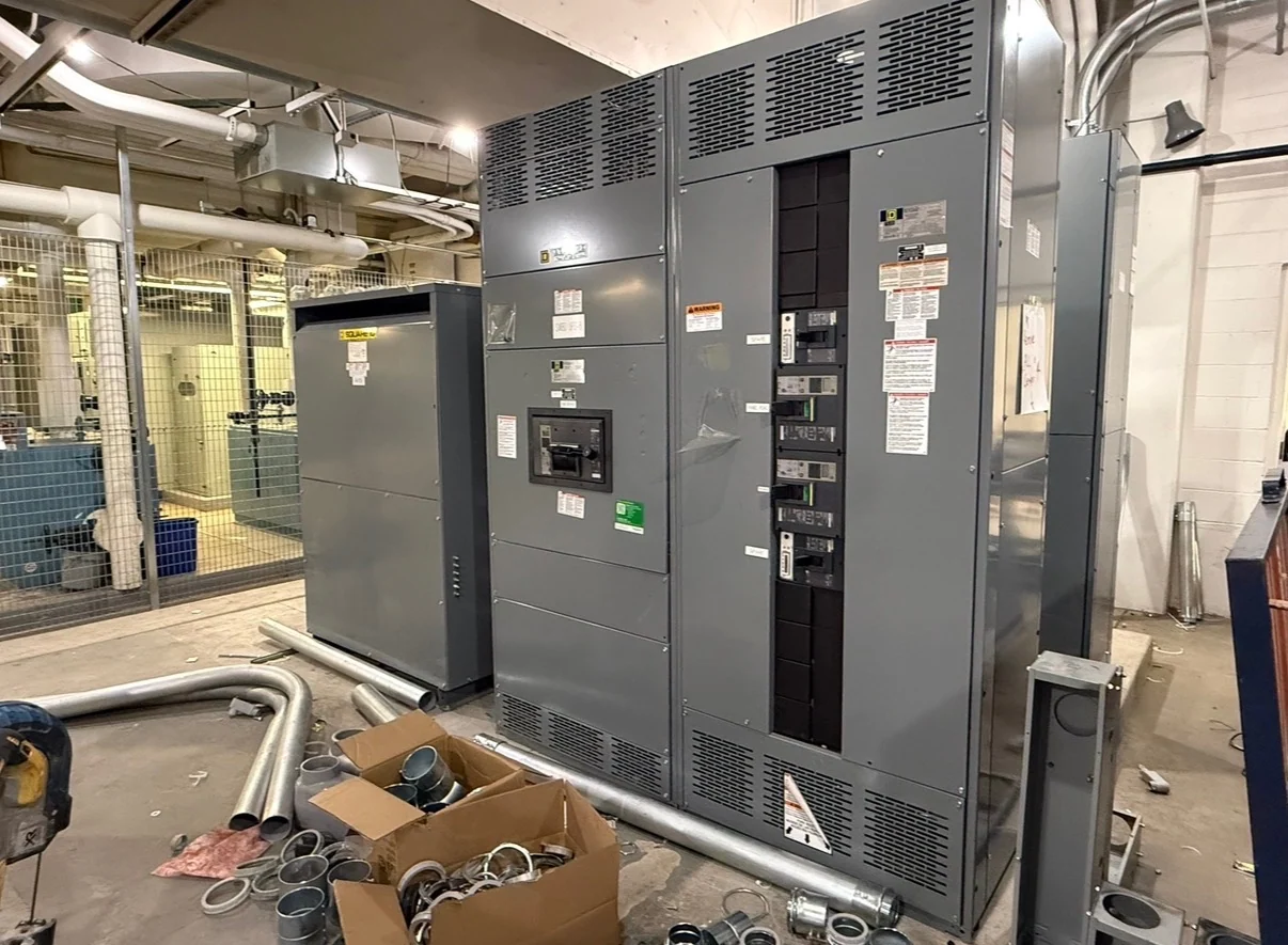
Service-Entrance Equipment in Plain Language
Service-entrance equipment is the electrical assembly at the point where power from a utility source enters a facility and passes to the premises distribution system. It commonly includes the service disconnecting means, overcurrent protection, bus conductors, metering provisions, grounding and bonding interfaces, and an enclosure suited to the installation. The exact arrangement depends on the utility connection, service voltage, phase and wire configuration, available fault current, and the facility's calculated demand. In practical terms, it defines the controlled boundary between incoming service conductors and downstream feeders, so the equipment must be designed around both utility requirements and the facility's electrical distribution plan.
The Utility-to-Facility Relationship
A service-entrance lineup connects several parties and design responsibilities that should be coordinated before fabrication. The utility may specify connection points, metering space, service disconnect preferences, grounding details, access rules, and approval submittals. The electrical engineer establishes load calculations, conductor sizes, fault-duty information, protection, and the intended feeder arrangement. The installer must confirm equipment dimensions, working space, cable routing, lifting access, and field termination conditions. A manufacturer uses these inputs to build new equipment to the project specification; no generic enclosure should be assumed to satisfy every utility or authority having jurisdiction.
Main Disconnect and Distribution Functions
The main disconnect provides the defined means of separating the facility's distribution equipment from the incoming service, while associated overcurrent devices protect conductors and downstream equipment according to the engineered design. From that point, bus sections and feeder devices can distribute power to building systems, process loads, or other distribution assemblies. A service-entrance design may also coordinate metering compartments, neutral and grounding provisions, surge protection, or source arrangements when the project calls for them. These functions are not interchangeable: a switchboard, panelboard, and switchgear lineup can serve different duties, so equipment terminology and one-line diagrams should match the actual application.
Inputs Needed for a Custom Build
A useful request for service-entrance equipment should identify nominal system voltage, frequency, phase, wire configuration, grounding method, continuous current, available fault current, service conductors, main and feeder devices, metering needs, enclosure environment, and physical dimensions. Include the latest one-line diagram, load schedule, utility criteria, site location, cable-entry direction, required access clearances, and any control or monitoring interfaces. It is also important to identify whether the assembly must coordinate with a transformer, generator, transfer equipment, or downstream distribution. Switchgear Builders manufactures new custom equipment in the United States, using American components and arranging nationwide shipping around the confirmed project scope.
Standards, Review, and Field Coordination
Service-entrance equipment selection depends on the electrical system and the serving utility’s requirements. The engineer, utility, authority having jurisdiction, and installation team should confirm applicable standards, construction details, markings, metering arrangements, grounding, working clearances, and inspection expectations for the specific project. UL 891 may be relevant to a particular switchboard application, but its applicability and any project-specific listing or capability must be confirmed before design approval; it should never be treated as a blanket assumption for every assembly. Review drawings before fabrication, reconcile utility comments, and record device data, wiring details, and agreed test requirements in the project package.
Planning Delivery and Installation
Large service equipment affects more than the electrical room schedule. The project team should coordinate shipping sections, approximate weights, lifting points, door and corridor dimensions, receiving access, storage conditions, cable pulling space, and the sequence for setting and joining sections. Confirm who supplies field-installed conductors, lugs, metering components, terminations, anchorage, and commissioning activities. A manufacturer quote should separate equipment scope from site work and state assumptions rather than leaving interfaces unclear. With a complete scope, a customer can request a new custom service-entrance build from the manufacturer and plan nationwide shipment without assuming inventory, price, or delivery timing before review.