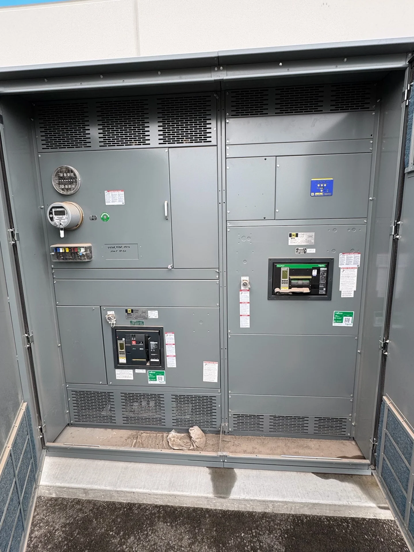
A Practical Definition of Switchgear
Switchgear is an engineered assembly of electrical switching devices, protective equipment, conductors, insulation, enclosures, and controls arranged to manage power distribution. Its job is broader than simply turning electricity on or off: it provides a controlled point for connecting sources and feeders, interrupting abnormal current, isolating sections for qualified work, and directing power through a defined system architecture. The exact arrangement depends on voltage class, continuous current, available fault current, grounding method, installation environment, and the operating sequence required by the facility. A switchgear lineup may include mains, feeders, bus sections, circuit breakers, switches, fuses, metering, relays, and control wiring, but those elements must be selected as a coordinated assembly rather than treated as unrelated parts.
How Switchgear Controls Power Flow
Switching equipment establishes the normal paths through which electricity reaches transformers, motors, panels, process loads, or other distribution points. A main device connects an incoming source to a bus, while feeder devices connect that bus to downstream circuits. A tie device can create a project-defined connection between bus sections or sources when the one-line diagram and interlocking scheme call for it. Operators and engineers must define which devices may be closed together, which combinations are prohibited, and what happens during maintenance or a source transfer. That operating logic affects device ratings, control circuits, labeling, access, metering, and the physical lineup. For a custom build, the single-line diagram and control narrative are essential starting points because they explain the intended power path more clearly than a product name alone.
Protection and Fault Interruption
Protection is the second major function of switchgear. Protective devices identify or respond to conditions such as overloads, short circuits, ground faults, or other project-defined abnormalities, then interrupt the affected circuit when their capabilities and settings are appropriate. Engineers compare available fault current with the interrupting or withstand duties of the devices and assembly, while coordination studies examine how upstream and downstream settings affect selectivity and clearing behavior. The equipment specification should therefore identify nominal voltage, frequency, phase and wire arrangement, continuous current, short-circuit requirements, protective-device types, trip functions, relay inputs, and grounding details. These decisions belong to the project engineering process; a general description of switchgear cannot establish a rating or guarantee a particular protective response.
Isolation, Access, and Physical Arrangement
Isolation allows a qualified electrical team to separate a circuit or equipment section from an energized source according to the approved operating and safety procedures. The desired isolation method may involve a disconnecting switch, a circuit breaker arrangement, visible isolation provisions, shutters, key interlocks, or other project-specific features. Physical design matters as much as the schematic: enclosure dimensions, cable entry, bus location, device access, working space, ventilation, lifting points, and shipping splits must fit the electrical room and installation path. Indoor and outdoor applications can impose different enclosure and environmental requirements. A manufacturer preparing new custom switchgear should receive room drawings, equipment orientation, conduit information, access constraints, and the installer’s interface requirements before finalizing the layout.
Switchgear Compared with Related Equipment
Switchgear is often confused with switchboards, panelboards, motor control centers, and transfer equipment because all can appear in a distribution system. The distinctions depend on construction, voltage range, device arrangement, fault duties, access, and the role assigned by the design. A panelboard commonly serves branch circuits or smaller feeders; a switchboard organizes mains and feeders in a distribution lineup; a motor control center groups motor starters, drives, and controls; a transfer switch changes a load connection between defined sources. Switchgear can incorporate switching and protective functions at a larger or more demanding distribution interface, but the correct choice requires reviewing the one-line diagram, ratings, environment, maintenance strategy, and applicable project requirements. Product labels alone should not replace that comparison.
What to Provide for a New Switchgear Specification
A useful inquiry for new switchgear identifies the system and the installation, not just a desired cabinet name. Provide the one-line diagram, nominal and maximum system voltage, frequency, phase, wire configuration, grounding method, continuous load calculations, available fault current, bus and feeder ratings, protective-device preferences, metering points, control voltage, interlocks, enclosure environment, dimensions, cable entry, and documentation expectations. Include site access, shipping destination, lifting limitations, planned lineup sections, and whether factory inspection or witnessed testing is part of the project plan. Switchgear Builders manufactures custom new electrical switchgear in the United States, using American components and supporting nationwide shipping; project-specific engineering review determines the appropriate construction, devices, drawings, testing scope, and any standard or listing requirements, including whether UL 891 applies.