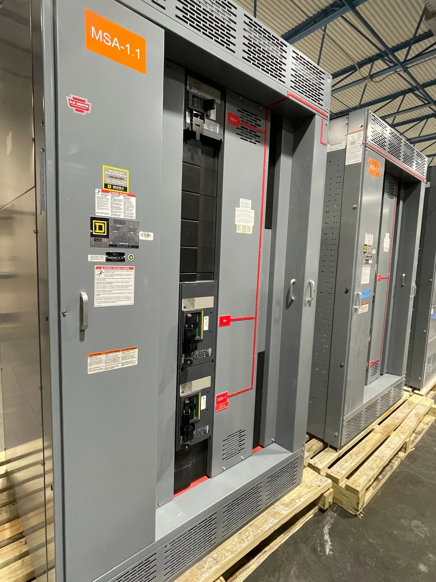
Bus Tie Definition
A bus tie is a connection and switching point between two bus sections in an electrical distribution system. Each section may normally be supplied by its own main device, while the tie remains open or closed according to the operating plan. Opening or closing the tie changes how sources and loads share the distribution path, so the arrangement must be defined with a one-line diagram, source characteristics, load requirements, and a clear switching sequence. A bus tie can be part of switchgear or a switchboard lineup; the equipment name does not by itself establish the correct rating, protection scheme, or operating method.
What the Tie Does in a Distribution Lineup
In a typical main-tie-main arrangement, two incoming sources feed separate bus sections and a tie device links those sections. With the tie open, each source can serve its assigned section independently. With the tie closed, the lineup may provide an alternate distribution path, subject to source capacity, paralleling rules, and the approved control sequence. Some designs use a tie for planned load transfers; others keep it available for a defined contingency. Engineers should state whether sources may be paralleled, which devices must be open before transfer, and whether manual, electrically operated, or automatic control is required.
Interlocking and Operating Sequence
The bus tie definition is incomplete without its interlocking logic. Mechanical key interlocks, electrical permissives, trapped-key arrangements, control switches, and protective relays may all help enforce the intended sequence, but the selected method depends on the project. A common sequence prevents two sources from being connected together unless paralleling has been specifically engineered and authorized. The design documentation should identify normal positions, transfer steps, source availability signals, local or remote controls, and the response to a failed permissive. Clear labels and an understandable operating procedure are as important as the physical tie device.
Ratings and Protection Questions
A tie device must be evaluated for the electrical duty created by the complete lineup, not simply for the current expected on one feeder. Important inputs include nominal voltage, phase and frequency, continuous current, available fault current, interrupting or withstand requirements, grounding method, conductor arrangement, and the characteristics of connected sources. Protection coordination should examine both normal and tie-closed conditions, because fault-current paths and relay or breaker selectivity can change when buses are connected. Arc-flash study inputs, metering needs, and control-power requirements should also be aligned with the project design.
Bus Tie Layout and Installation Planning
Physical planning affects whether a bus tie is practical to build and install. The lineup layout should show bus-section boundaries, device compartments, cable or busway interfaces, control wiring routes, lifting points, working clearances, and access for operation and maintenance. Indoor and outdoor installations may require different enclosure and environmental considerations. The installer also needs the shipping split, equipment dimensions, approximate weights, anchorage information, and the movement path into the electrical room. Coordinating these details before fabrication reduces conflicts between the electrical design, structural supports, conduit, and site access.
Specifying a New Bus Tie Assembly
When requesting a new custom bus tie assembly, provide the one-line diagram, source and load schedule, electrical ratings, desired normal device positions, transfer narrative, interlocking philosophy, control voltage, metering points, enclosure conditions, dimensions, cable entry direction, documentation requirements, and destination for nationwide shipping. Switchgear Builders manufactures, builds, and supplies new electrical switchgear in the United States, custom to project specifications, using American components. The final configuration, applicable standards, and any project-specific listing requirement must be reviewed and confirmed for the particular assembly before an order is placed.