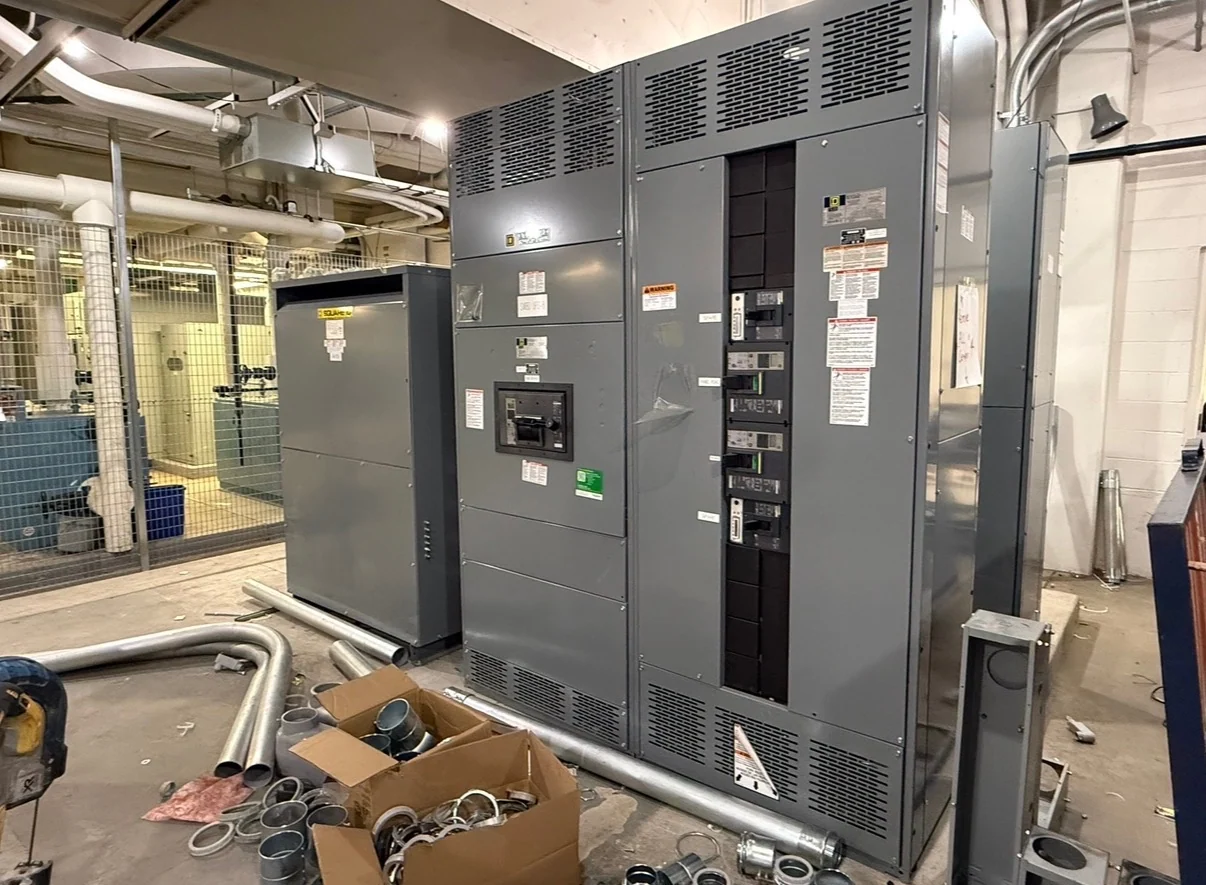
Continuous Current Rating Definition
A continuous current rating is the amount of current an electrical assembly, bus, feeder, or device is intended to carry continuously under the conditions established for its design. It is not simply the largest momentary reading expected during operation. The rating must be considered with system voltage, phase arrangement, frequency, conductor material, enclosure, ambient conditions, installation orientation, and the applicable engineering requirements. In practical terms, the rating helps determine whether a lineup can carry its calculated load without treating temporary overload capability as normal operating capacity.
How the Rating Relates to Real Loads
Load calculations provide the starting point for selecting continuous current capacity. Engineers typically examine connected loads, demand assumptions, motor operation, heating equipment, power conversion equipment, and anticipated expansion rather than adding nameplate values without review. A feeder may have a different required rating from a main bus because their loads, protection, and operating duty differ. The specification should identify which portions of the assembly carry each load and whether any source, tie, or transfer condition changes the current that can flow through a section. Demand factors should be traceable to the design basis, especially where several loads operate at different times. If a facility expects added motors, process skids, tenant circuits, or generation, state that planning assumption explicitly so spare capacity is not confused with an available fault rating or an automatic right to increase protection settings.
Bus, Feeder, and Device Coordination
A switchgear or switchboard lineup is a coordinated assembly, so the continuous current rating of one component cannot be evaluated in isolation. Bus conductors, connections, circuit breakers, switches, cable terminations, metering provisions, and enclosure arrangements all need compatible ratings for the intended configuration. Protective-device frame and sensor choices should be reviewed alongside conductor capacity and calculated load. A higher-rated main does not automatically make every feeder or bus section suitable for that current; each path and operating mode should be documented separately. Coordination also includes terminations and interfaces outside the enclosure. Cable size, lug selection, bus joints, neutral arrangements, grounding conductors, and control equipment should match the documented current path. Where a lineup can be rearranged, the review should identify the limiting section instead of relying on the nameplate of the largest device.
Environmental and Installation Inputs
Operating conditions can influence the rating selected for an assembly. Ambient temperature, indoor or outdoor placement, solar exposure, altitude where relevant, ventilation, enclosure construction, spacing, cable entry, and proximity to heat-producing equipment should be identified before fabrication. Maintenance access and the physical arrangement can also affect how components are installed and connected. The project team should provide site conditions and installation constraints so the manufacturer can evaluate the proposed design rather than applying a generic continuous current number detached from the actual equipment environment. Conditions may differ between normal operation and an emergency arrangement, such as a source transfer or temporary generator connection. Those scenarios should be described with expected current flow and duration. A rating decision that ignores the installation room or the intended ventilation path can produce an unsuitable specification even when the arithmetic load total appears correct.
Specifying a New Custom Assembly
When requesting new custom switchgear from an American manufacturer, provide the one-line diagram, nominal system voltage, phase and wire configuration, frequency, grounding method, available fault current, calculated loads, source details, feeder schedule, enclosure location, dimensions, cable-entry direction, and future-capacity expectations. Identify main, tie, and feeder operating sequences where applicable. Switchgear Builders manufactures new equipment to project specifications, uses American components, and can coordinate nationwide shipping; final component selections and ratings remain subject to project engineering review.
Review, Documentation, and Acceptance
Before a continuous current rating is accepted, compare the equipment schedule, one-line diagram, protection study inputs, layout drawings, and installation requirements for consistency. Ask which rating applies to the complete assembly, each bus section, each feeder, and each operating configuration. Record assumptions about load diversity, ambient conditions, future circuits, and source availability in the project documents. If UL 891 could apply to a switchboard project, its applicability and any project-specific listing or verification must be confirmed rather than assumed.