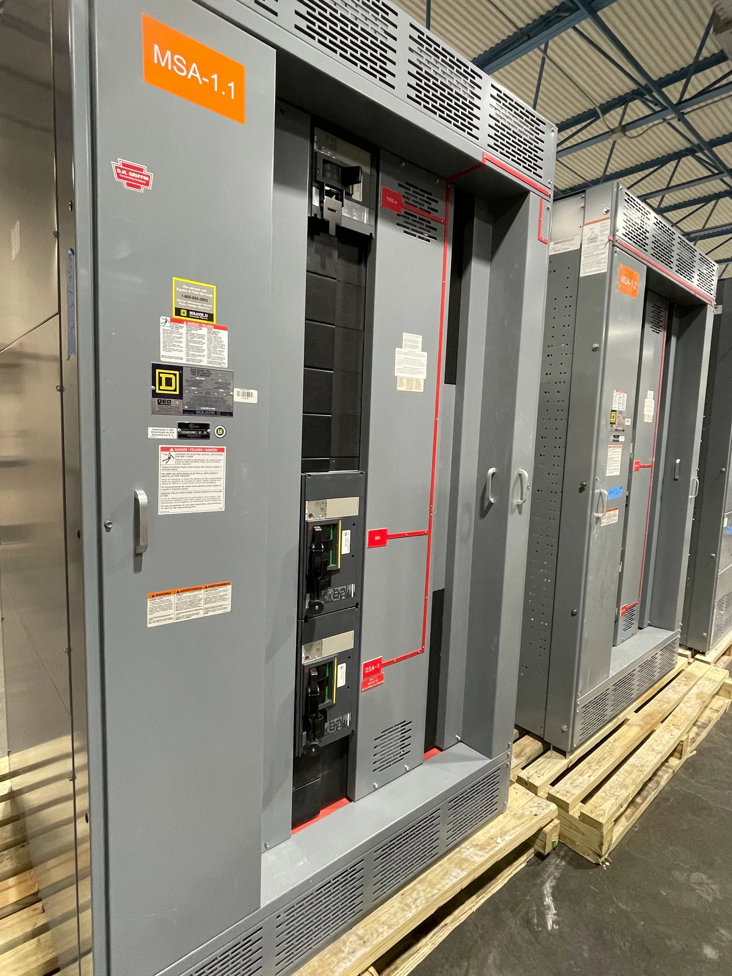
Main Breaker Definition
A main breaker is the principal circuit breaker that controls and protects power entering an electrical assembly, such as a switchboard, switchgear lineup, or service-distribution arrangement. It provides a means to open the primary supply path and responds to specified overcurrent conditions through its trip mechanism. The word main describes its position and system role, not one universal frame size, voltage, trip unit, or enclosure. A project engineer must identify the actual source, conductors, equipment configuration, and governing requirements before selecting the device. Switchgear Builders manufactures new electrical switchgear in the United States, custom to project specifications, with American components and nationwide shipping for customer-defined applications.
What the Device Does
In normal operation, the main breaker permits the source to energize a bus or distribution section while allowing authorized personnel to disconnect that section when the design and operating procedure call for it. During an overcurrent event, its trip unit can signal opening according to its available functions and settings. That action is part of a coordinated protection scheme; it is not a substitute for grounding design, equipment bonding, arc-flash analysis, or safe work practices. A main breaker may also provide auxiliary contacts, shunt-trip control, undervoltage release, metering interfaces, or interlocking provisions when those requirements are defined in the equipment specification rather than assumed from the name alone.
Main Breaker Versus Main Disconnect
The terms main breaker and main disconnect are related but not interchangeable. A disconnect describes the function of isolating a circuit or assembly, while a breaker combines switching with overcurrent interruption within its rated application. Some installations use a circuit breaker as the main disconnect; others use a separate disconnecting means with upstream or downstream overcurrent protection. The correct arrangement depends on the service or feeder topology, number of sources, utility interface, available fault current, conductor ampacity, and applicable project requirements. Clear one-line diagrams and equipment schedules should identify which device is the main, what it feeds, and how it operates with ties, generators, or transfer equipment.
Ratings That Must Be Defined
A useful main breaker specification states system voltage, phase and frequency, continuous current, interrupting rating, short-circuit duty for the assembly where applicable, trip characteristics, and enclosure or installation conditions. It should also address neutral treatment, grounding and bonding interfaces, cable or bus connections, space constraints, control power, metering, and whether the breaker is fixed or removable. Available fault current at the installation point is essential because a device rating cannot be selected from load current alone. Future load growth may affect the lineup and bus design, but it should be documented as a design input rather than treated as an automatic capacity promise.
Coordination and Operating Sequence
Main-breaker settings are reviewed with feeder breakers, protective relays, transformers, generators, and other sources so a fault can be interrupted by the intended device when practical. Time-current characteristics, instantaneous functions, short-time delay, ground-fault functions, selective coordination objectives, and source interlocks may all influence the final choice. A main-tie-main lineup, emergency source, or maintenance bypass can make the operating sequence more important than a simple open-and-close description. The design team should document normal and alternate source states, tie permissives, trip signals, lockout behavior, and reset expectations before fabrication, then align the control wiring and drawings with that approved sequence.
Specifying a New Main Breaker Assembly
For a manufacturer quote, provide the latest one-line diagram, load schedule, source information, fault-current study or available fault-current value, physical dimensions, cable-entry direction, installation environment, and required documentation. Include feeder count, bus arrangement, metering, communication, control voltage, interlocks, shipping destination, and the responsible engineer or authority for technical review. Switchgear Builders can use those inputs to develop new custom electrical switchgear for the defined application, clarify open design questions, and supply the equipment nationwide. Switchgear Builders uses American components; ratings, features, and project-specific requirements should be confirmed during engineering review.