What Selective Coordination Is Intended to Achieve
Selective coordination of electrical protection is the planning objective that a downstream protective device clears a fault while upstream devices remain closed whenever the system conditions and device operating ranges allow that result. The purpose is not simply to choose larger breakers at the service entrance. It is to preserve power to unaffected portions of a facility, limit unnecessary outages, and make the distribution system's response understandable to operators. A switchgear guide should therefore connect every protective device to its source, downstream circuits, available fault current, and intended operating sequence before any coordination conclusion is made.
Start With a Complete Distribution Model
A useful review begins with a current one-line diagram and a device schedule that identify utility or generator sources, transformers, switchgear sections, feeders, panelboards, motor loads, and significant branch circuits. Gather nominal voltage, phase and grounding arrangement, transformer impedance, conductor information, device frame and sensor ratings, trip-unit functions, fuse data where applicable, and calculated available fault current at each relevant bus. Include alternate sources, bus ties, transfer equipment, and operating states; a lineup that coordinates on normal utility service may behave differently when a generator or tie supplies the same downstream device.
Read Time-Current Curves as a System
Time-current curves, often called TCCs, show how long a protective device may take to operate at different current levels. The reviewer compares the downstream device curve with the upstream device curve, seeking separation through the portions of the curves that matter for overloads, short circuits, and instantaneous or magnetic operation. Curve bands represent tolerances rather than a single guaranteed trip time, so apparent spacing must be interpreted conservatively. Transformer inrush, motor starting current, conductor damage limits, and device clearing time can change the practical boundary between coordination and an unwanted upstream operation.
Balance Coordination Against Protection
Coordination is not an instruction to delay every upstream device indefinitely. Longer delays can increase incident energy, equipment stress, or conductor exposure during a fault, while aggressive instantaneous settings can sacrifice selectivity for a severe fault. Engineers commonly examine long-time, short-time, instantaneous, and ground-fault functions where those functions exist, then compare settings with conductor ampacity, equipment withstand, breaker interrupting capability, and the study's arc-flash assumptions. The final settings should reflect the engineer's protection philosophy and the operating state, not a visual preference for widely separated curves.
Design Inputs for Custom Switchgear
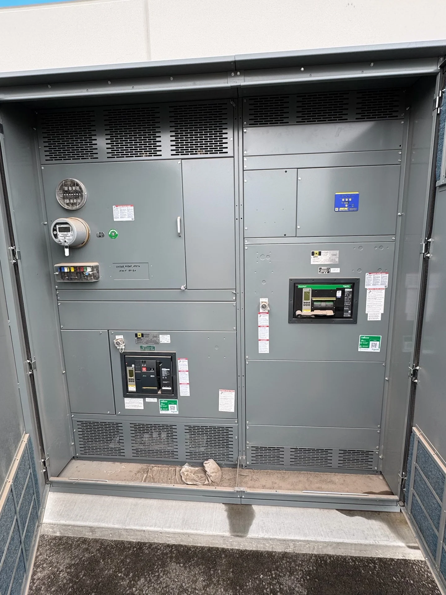
When a manufacturer builds new custom switchgear, the coordination package should accompany the equipment requirements rather than arrive as an afterthought. Provide the approved one-line diagram, device schedule, target settings or study assumptions, bus arrangement, source information, control and interlock sequence, cable entry constraints, and any required metering or communication interfaces. Switchgear Builders can use those project inputs to coordinate enclosure layout, bus sections, protective devices, control wiring, identification, and documentation. Component selection and final arrangement remain subject to the electrical engineer's review, the specified devices, and the requirements established for that project.
Check Multiple Operating Scenarios
A coordination study should test more than the easiest normal case. Review maximum and minimum utility fault levels when they affect device behavior, generator contribution, transformer energization, tie-open and tie-closed arrangements, transfer sequences, and any maintenance configuration that changes the source path. Verify that a setting acceptable for one source does not leave another source inadequately protected or cause an upstream device to trip first. Document assumptions, unavailable data, and exceptions clearly so the owner, engineer, installer, and equipment manufacturer share the same interpretation of the switchgear design.
Turn the Review Into Buildable Documentation
The practical deliverable is more than a plotted curve. It should identify each device, its settings or selected characteristics, the source and load relationship, applicable fault-current values, coordination limits, and unresolved decisions. Final submittal drawings and schedules should match the approved design, including breaker positions, control terminals, labels, interlocks, and any field-adjustable functions. Before release for fabrication, ask who owns the settings, who verifies field conditions, what testing is required, and how revisions will be controlled. This discipline helps the new American-built assembly arrive with information that supports project-specific installation and commissioning.