Start With the Distribution Problem
Useful switchgear guides begin with the electrical system rather than a catalog label. Define the source arrangement, nominal voltage, phase and wire configuration, frequency, grounding method, continuous load, future capacity, and available fault current. Then identify whether the assembly serves a service entrance, transformer secondary, generator, motor loads, process feeders, or a combination. This information helps distinguish switchgear from switchboards, panelboards, motor control centers, and transfer equipment. A manufacturer can build new electrical switchgear in the United States custom to specification, but the equipment concept still depends on a coordinated one-line diagram and project requirements.
Use Ratings to Shape the Equipment
Switchgear selection should connect system duty to physical construction. Review continuous-current ratings for the main, bus, and feeders; interrupting ratings for protective devices; and the assembly short-circuit rating or withstand requirement specified by the project. Consider enclosure type, indoor or outdoor exposure, working clearances, cable entry, bus material, grounding provisions, metering, and access for operation and maintenance. Protective-device coordination may change breaker frame sizes, trip functions, fuses, relays, or control wiring. Arc-flash study results can influence settings and design decisions, while arc-resistant construction is a separate project-specific requirement that must not be presumed. Confirm whether UL 891 applies to the particular switchboard or switchgear scope and whether any requested listing or verification is available for that exact project.
A practical electrical distribution guide also records what the equipment must connect to. Provide transformer data, utility information, generator characteristics, feeder conductor details, motor starting conditions, grounding requirements, and the intended operating sequence. For a main-tie-main arrangement, explain which sources may be closed, how the tie is controlled, and what interlocks are required. For transfer equipment, describe open- or closed-transition intent and the loads that may tolerate an interruption. Physical information matters equally: room dimensions, access paths, floor elevations, lifting limitations, cable bending space, ventilation, and conduit or busway interfaces should be reviewed before drawings are finalized. These inputs reduce redesign caused by an electrically correct lineup that cannot be installed or serviced in its assigned space.
Prepare a Clear Custom-Build Inquiry
When requesting a custom switchgear quote, send a coherent package instead of a product name alone. Include the latest one-line diagram, load schedule, fault-current study or available fault-current value, equipment schedule, site conditions, enclosure requirements, dimensions, device preferences, metering needs, control schematics, communications expectations, and required submittal documents. Identify which details are fixed and which remain open for engineering review. State the destination for nationwide shipping, receiving constraints, preferred shipping splits, and any lifting or access considerations. Switchgear Builders uses American components; state and confirm component-origin expectations, substitutions, and acceptable equivalents in the project documentation.
Compare manufacturer proposals on an aligned scope. Check whether each quotation includes the same mains and feeders, protective functions, bus arrangement, enclosure, controls, metering, drawings, test records, freight assumptions, and exclusions. Ask how deviations from the submitted one-line will be identified and how approval comments are incorporated. Do not compare a low number with an incomplete scope against a higher number that includes engineering and documentation. For a replacement or expansion, provide existing dimensions, connection points, equipment-room constraints, and outage coordination information while making clear that the new assembly remains subject to field verification and qualified engineering review. A disciplined comparison protects the project from discovering important differences after an order is placed.
Coordinate Fabrication and Installation
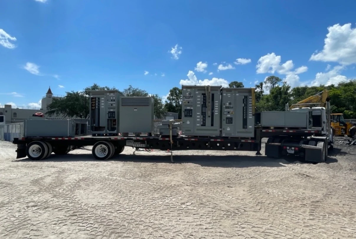
Installation planning should begin while the lineup is being designed. Review shipping sections, approximate weights, lifting points, center of gravity information when available, door swing, removable components, joining hardware, and the route from receiving to the electrical room. Coordinate housekeeping pads, anchors, sleeves, conduit, cable tray, busway connections, grounding conductors, and required working space with the electrical contractor and design team. The manufacturer can supply new equipment and coordinate project documentation, while site preparation, rigging, field connections, and final installation responsibilities must be assigned explicitly.
Plan Verification Before Energization
A sound guide treats inspection and testing as a project plan, not an implied promise. Agree on drawing review milestones, enclosure and bus inspection points, device identification, wiring checks, continuity checks, insulation testing where applicable, mechanical operation, interlock operation, metering verification, and control-function tests. Acceptance criteria should identify the responsible parties, instruments or records required, witness points, and how exceptions will be documented. Device settings should be reviewed against the approved coordination study, and field commissioning should be performed by qualified personnel under the project’s safety procedures. Any test scope, factory acceptance test, or documentation package must be defined for the specific assembly rather than assumed from a generic switchgear description.
Build a Useful Operating Record
The final equipment record should let authorized personnel understand the lineup without reconstructing its design. Organize the approved one-line, wiring diagrams, layout drawings, device schedules, nameplate information, settings, interlock descriptions, test results, shipping splits, installation notes, and maintenance references. An operating procedure should describe normal source positions, transfer or tie sequences, isolation steps, inspection boundaries, and the qualifications required for switching decisions. Because every project has different sources, loads, controls, and local requirements, the record should be reviewed with the owner, engineer, installer, and commissioning team before operation.