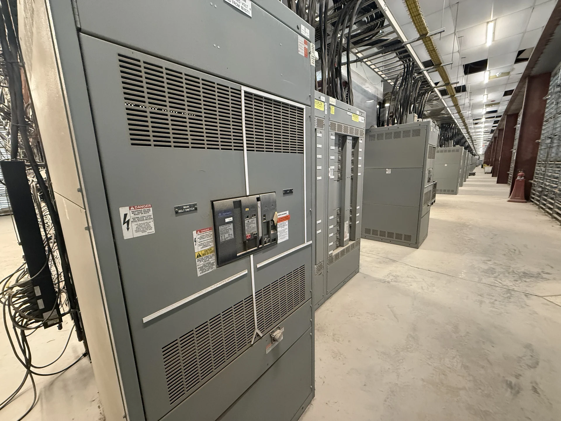
Start with the Utility Service Basis
Coordinating switchgear with the utility begins before an equipment layout is frozen. Request the service voltage, phase and wire arrangement, frequency, available fault current, grounding method, service point, and utility-owned versus customer-owned boundaries. Confirm whether the project is a new service, an alteration, a replacement, or an added source. Those distinctions affect the incoming section, disconnecting means, metering interface, conductor termination space, and review path. A one-line diagram should show every source, transformer, main device, bus tie, feeder, and generator or energy resource connection that could influence the service arrangement.
Define Metering and Service Interfaces
Metering details must be treated as design inputs rather than a late accessory. Ask the utility for its current metering standard, instrument-transformer requirements, CT ratios or classes where applicable, meter socket or compartment arrangement, test-switch expectations, sealing provisions, and location rules. Establish who furnishes each transformer, meter enclosure, conduit, terminal, and communication connection, then show those responsibilities on the submittal drawings. A manufacturer can build new custom switchgear around the confirmed interface, but the final arrangement depends on utility approval, equipment dimensions, conductor routing, and the authority having jurisdiction for the installation.
Coordinate Fault Duty and Protection
The utility’s fault-current information is essential for selecting an appropriate new switchgear assembly and its protective devices. Obtain the available fault current at the service point, the utility source impedance or equivalent data when provided, transformer information, and any required interrupting, withstand, or bracing criteria. Compare those inputs with the calculated load, continuous-current needs, feeder duties, and downstream coordination study. Protection discussions should identify main-device functions, ground-fault requirements where applicable, relay inputs, trip settings, and utility preferences without assuming a setting before an engineer completes the study. A revised utility value can require a design review rather than a simple paperwork change.
Map Approval Milestones
A useful utility coordination plan names the submission and approval milestones in sequence. Typical checkpoints may include preliminary one-line review, service application acceptance, metering arrangement approval, protection or relay review, equipment drawing review, inspection scheduling, and authorization to energize; the exact sequence belongs to the serving utility and project jurisdiction. Assign an owner and required document to each checkpoint, and record open comments instead of relying on informal assumptions. When a customer buys new switchgear directly from an American manufacturer, the quote package should identify which utility documents are available, which remain pending, and which design choices are conditional on written approval.
Build Utility Comments into the Submittal
Before fabrication, reconcile the utility’s comments against the one-line diagram, enclosure elevations, wiring diagrams, metering details, and nameplate information. Check that service conductors can reach their intended lugs, instrument-transformer polarity and access are represented, phases and neutral paths are clear, and utility seals or restricted compartments are physically feasible. Distinguish utility requirements from owner preferences and installer means-and-methods. This review is also the right point to confirm shipping splits, lifting provisions, field connections, and document revisions for a nationwide shipment, so the delivered assembly can be received and installed against an agreed drawing set.
Plan Changes, Witnesses, and Closeout
Utility coordination continues through inspection and energization, so preserve a controlled record of approved drawings, comment responses, test requirements, and field changes. Ask whether the utility requires a witness for metering checks, relay verification, phase identification, or other acceptance steps, and coordinate those obligations with the utility’s confirmed availability. The manufacturer’s documentation package should match the final configuration and identify unresolved responsibilities clearly. If the utility changes service data, metering rules, or protection criteria, pause fabrication or installation decisions long enough for qualified electrical professionals to evaluate the effect on the new custom switchgear.