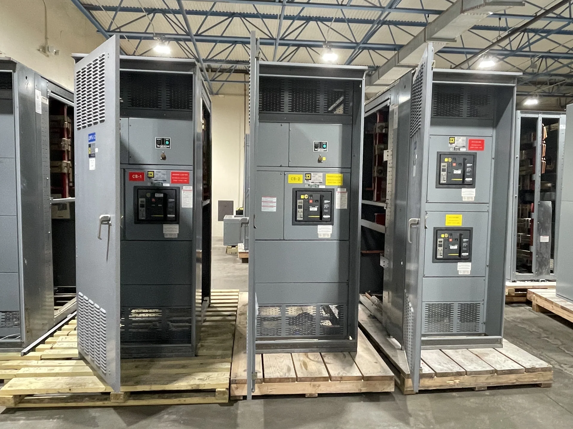
Start With the Utility Service Interface
Utility metering requirements for switchgear begin at the boundary between the serving utility and the customer electrical system. Before a design is finalized, identify the service voltage, phase arrangement, frequency, grounded-conductor configuration, service disconnect arrangement, and point of delivery. Request the utility’s current service manual, metering standards, approved equipment details, and review process rather than relying on a generic switchgear specification. These inputs determine where line and load terminations belong, how the metering section relates to the main device, what access the utility expects, and which information must appear on drawings. A manufacturer can build new custom switchgear to the approved project requirements, with American components and nationwide shipping, after the electrical and utility interfaces are defined.
Define Metering Type and Ownership
The phrase utility metering can describe several arrangements, so the specification should name the actual scheme. Clarify whether the utility requires self-contained metering, instrument-transformer metering, a separate meter cabinet, or a utility-furnished meter installed in a customer-provided compartment. Confirm who furnishes current transformers, potential transformers, test switches, meter sockets, shorting provisions, terminal blocks, seals, and communication accessories. Ownership affects access, wiring responsibility, inspection sequence, and the boundary between factory assembly and field installation. If revenue metering and customer monitoring are both required, keep their functions distinct in the drawings and identify any isolation, test, or communications provisions requested by the utility or engineer.
Coordinate Space, Access, and Sealing
A metering section must fit the electrical arrangement and the people who will inspect, connect, read, test, and maintain it. Provide the manufacturer with the required compartment dimensions, meter orientation, door swing, viewing needs, cable entry direction, bending space, conductor size, termination method, and access restrictions. Ask the utility whether doors, covers, fasteners, barriers, or removable panels require sealing or utility-only access. Coordinate the metering compartment with the main breaker, bus, pull sections, wireways, and service clearances so that a compact lineup does not create an installation conflict. The final layout should show external dimensions, shipping splits, lifting points, and field connection locations for review before fabrication.
Match Ratings and Protection Information
Metering details cannot be separated from the electrical equipment rating. The project team should provide calculated load, continuous current, nominal voltage, available fault current, service grounding method, conductor information, and the interrupting or short-circuit requirements applicable to each device and assembly. Confirm instrument-transformer ratios, accuracy class, burden, insulation requirements, and polarity or phase-marking conventions with the responsible engineer and utility; these are design inputs, not assumptions. Review the main protective device, bus rating, feeder arrangement, and metering connection together so the lineup reflects the intended one-line diagram. Any requirement for a particular enclosure environment, temperature condition, or installation exposure should also be stated in the equipment schedule.
Plan Drawings, Review, and Acceptance
A strong submittal package makes utility review more predictable by showing the service one-line, metering schematic, physical elevation, compartment boundaries, terminal identification, wiring schedule, device data, and connection points. Mark utility-furnished versus manufacturer-furnished items, and identify field-installed conductors or accessories. Establish who submits drawings to the utility, who answers comments, and whether utility approval is required before fabrication. If a project references UL 891, confirm its applicability, construction requirements, and any project-specific listing or test evidence for the proposed assembly; the reference does not establish a blanket listing for every switchgear type. Acceptance criteria, inspection points, and test records should be agreed by the project stakeholders.
Prepare a Complete Manufacturer Inquiry
For a useful custom switchgear quote, send the manufacturer the latest one-line diagram, utility service requirements, site voltage and frequency, available fault current, load schedule, dimensions, indoor or outdoor application, cable entry details, metering method, utility comments, and required documentation. Include the destination for nationwide shipping and identify receiving constraints, access limitations, and whether the lineup will ship in sections. State the desired operating sequence and any coordination study inputs without prescribing a device or rating that has not been engineered. Switchgear Builders manufactures and supplies new electrical switchgear in the United States, custom to specification, using American components; project-specific design review remains necessary to confirm the final arrangement and utility interface.