Start With the Electrical System Description
120/240 V switchgear and distribution equipment is not defined by voltage alone. The design team should identify whether the source is a single-phase, three-wire system, how the grounded conductor is treated, and where the equipment connects to the service or feeder arrangement. Confirm nominal voltage, frequency, phase sequence where applicable, grounding method, available fault current, and the intended load profile before selecting an enclosure or protective device. Switchgear Builders manufactures new electrical switchgear in the United States, custom to specification, using American components and offering nationwide shipping. A useful inquiry includes the one-line diagram, service information, installation environment, and the project requirements that govern the final assembly.
Balance Loads Across the Two Line Conductors
In a 120/240 V single-phase, three-wire arrangement, 120 V loads connect from either ungrounded conductor to the grounded conductor, while 240 V loads connect across the two ungrounded conductors. The equipment plan should show how branch and feeder loads are distributed so the calculated demand, conductor sizing, and protective-device selection reflect the actual operating arrangement. Load balance is a design objective rather than an assumption; motor starting, heating equipment, receptacle demand, and future circuits can change the current on each leg. The switchgear layout should leave clear identification for each circuit and coordinate with the electrician's installation drawings.
Specify Main and Feeder Protection
Protective devices must be selected from the system's calculated load, conductor ampacity, available fault current, and equipment configuration. For a 120/240 V lineup, clarify whether the main device and feeders are two-pole, single-pole, or another project-defined arrangement, and identify any shared grounded-conductor provisions that affect wiring and termination space. Interrupting capability, continuous current, trip functions, accessory requirements, and coordination settings should be reviewed by the responsible electrical engineer. A manufacturer quote becomes more useful when it includes device schedules, desired enclosure dimensions, cable entry direction, metering needs, and any required control or interlock sequence.
Coordinate Grounding and Bonding
Grounding and bonding details deserve a dedicated review because the correct connection point depends on whether the assembly is service equipment or downstream distribution equipment. Document the grounded conductor, equipment grounding conductor, bonding points, grounding electrode interface, and any system-specific separation requirements on the drawings. The installer also needs practical information about lug locations, conductor routing, barriers, and access for inspection. Do not infer these details from a familiar panel arrangement: the source, service boundary, and project electrical design control the final configuration. Switchgear Builders can use those engineering inputs to build a new custom assembly that matches the specified interfaces.
Plan the Physical Distribution Assembly
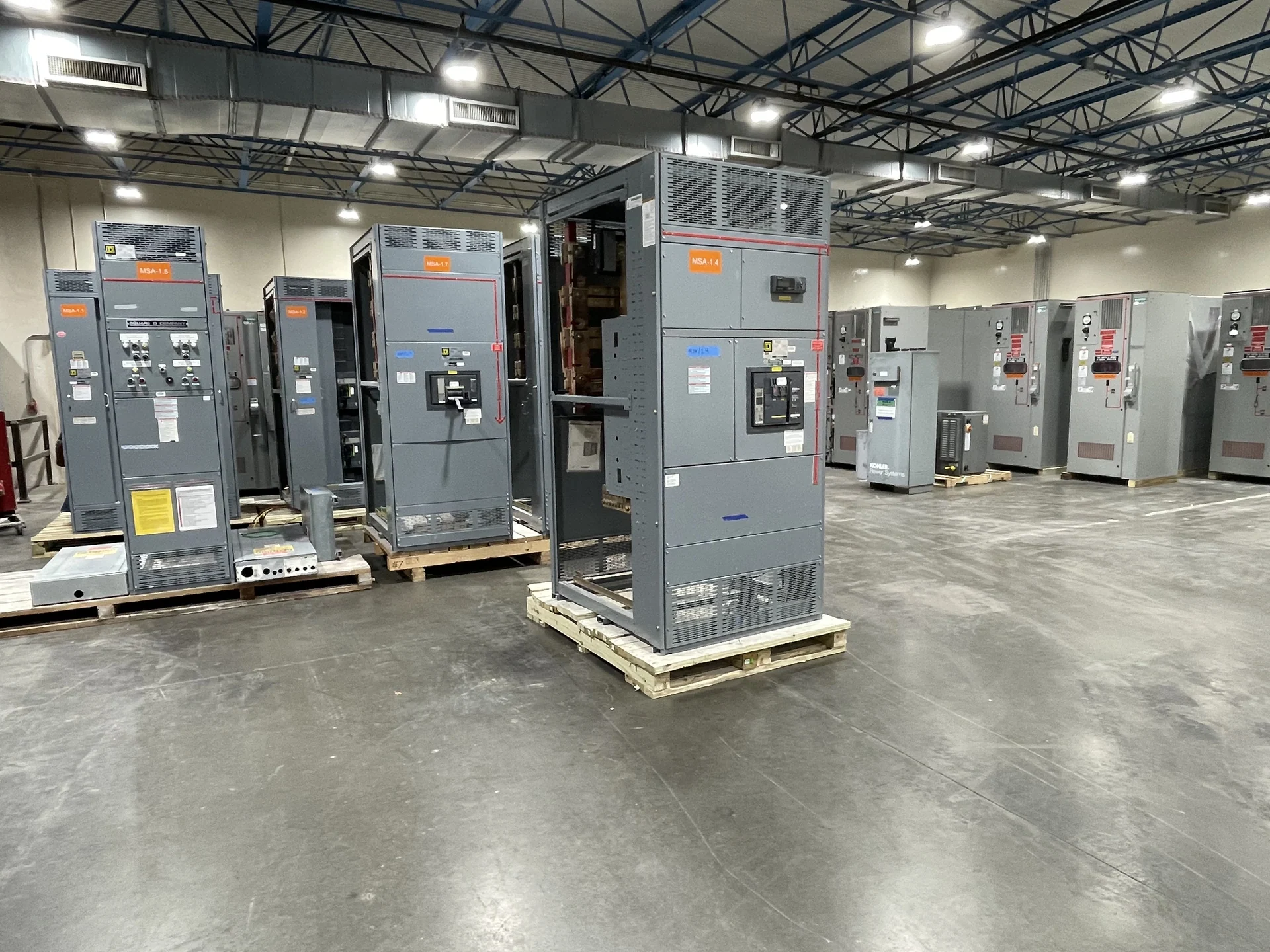
Electrical performance and physical fit must be developed together. Provide the available room dimensions, working-space constraints, conduit or cable locations, access path, mounting surface, environmental conditions, and desired future-circuit capacity. Identify whether the lineup needs front access, rear access, metering sections, distribution compartments, or a particular sequence of mains and feeders. Drawings should show overall dimensions, device locations, wireway space, terminal points, and lifting or shipping splits where the assembly size requires them. These details help the manufacturer avoid a design that meets an electrical schedule but cannot be installed or maintained within the project's actual space.
Review Documents, Testing, and Delivery Inputs
Before fabrication, align the submittal package with the project team: one-line and elementary diagrams, layout drawings, device data, nameplate information, wiring schedules, and the agreed inspection or electrical test plan. If a specification references UL 891, determine whether that standard applies to the particular assembly and confirm any project-specific listing or verification requirements before the design is finalized; applicability is not automatic for every 120/240 V configuration. For nationwide shipping, provide the destination, receiving hours, site access information, packaging expectations, and responsibility for unloading or rigging. Those logistics are part of a complete equipment plan, not an afterthought.